Advertisements
Advertisements
Question
In series LCR circuit, the plot of Imax vs ω is shown in figure. Find the bandwidth and mark in the figure.

Advertisements
Solution
We know that bandwidth = (ω2 – ω1).
Where ω1 and ω2 are two frequencies where the current amplitude of LCR circuit becomes `12sqrt(12)` times (i.e., Irms) the value of current is maximum at resonant frequency.
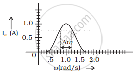
`I = E_0/sqrt(2) = 1/sqrt(2)` = 0.707 Amp
From graph ω1 and ω2 at 0.707A current is 0.8 and 1.2 rad/sec.
So Bandwith ω2.ω1 = 1.2 – 0.8 = 0.4 rad/sec.
APPEARS IN
RELATED QUESTIONS
In a series LCR circuit, VL = VC ≠ VR. What is the value of power factor?
A series LCR circuit is connected across an a.c. source of variable angular frequency 'ω'. Plot a graph showing variation of current 'i' as a function of 'ω' for two resistances R1 and R2 (R1 > R2).
Answer the following questions using this graph :
(a) In which case is the resonance sharper and why?
(b) In which case in the power dissipation more and why?
In a series LCR circuit, obtain the condition under which the impedance of the circuit is minimum ?
In a series LCR circuit, obtain the condition under which watt-less current flows in the circuit ?
A series LCR circuit is connected to an ac source. Using the phasor diagram, derive the expression for the impedance of the circuit. Plot a graph to show the variation of current with frequency of the source, explaining the nature of its variation.
A coil having an inductance L and a resistance R is connected to a battery of emf ε. Find the time taken for the magnetic energy stored in the circuit to change from one fourth of the steady-state value to half of the steady-state value.
A solenoid having inductance 4.0 H and resistance 10 Ω is connected to a 4.0 V battery at t = 0. Find (a) the time constant, (b) the time elapsed before the current reaches 0.63 of its steady-state value, (c) the power delivered by the battery at this instant and (d) the power dissipated in Joule heating at this instant.
A constant current exists in an inductor-coil connected to a battery. The coil is short-circuited and the battery is removed. Show that the charge flown through the coil after the short-circuiting is the same as that which flows in one time constant before the short-circuiting.
Consider the circuit shown in figure. (a) Find the current through the battery a long time after the switch S is closed. (b) Suppose the switch is again opened at t = 0. What is the time constant of the discharging circuit? (c) Find the current through the inductor after one time constant.

Answer the following question.
What is the phase difference between the voltages across the inductor and the capacitor at resonance in the LCR circuit?
The selectivity of a series LCR a.c. circuit is large, when ______.
In an L.C.R. series a.c. circuit, the current ______.
At resonant frequency the current amplitude in series LCR circuit is ______.
To reduce the resonant frequency in an LCR series circuit with a generator
The phase diffn b/w the current and voltage at resonance is
Which of the following statements about a series LCR circuit connected to an ac source is correct?
Draw a labelled graph showing variation of impedance (Z) of a series LCR circuit Vs frequency (f) of the ac supply. Mark the resonant frequency as f0·
