Advertisements
Advertisements
Question
Which of the following statements about a series LCR circuit connected to an ac source is correct?
Options
If the frequency of the source is increased, the impedance of the circuit first decreases and then increases.
If the net reactance (XL - XC) of the circuit becomes equal to its resistance, then the current leads the voltage by 45°.
At resonance, the voltage drop across the inductor is more than that across the capacitor.
At resonance, the voltage drop across the capacitor is more than that across the inductor.
Advertisements
Solution
If the net reactance (XL - XC) of the circuit becomes equal to its resistance, then the current leads the voltage by 45°.
Explanation:
For an LCR circuit,
`tanphi = (X_L - X_C)/R`
If XL - XC = R
`tanphi = R/R`
`tanphi = 1 ⇒ phi = 45^circ`
APPEARS IN
RELATED QUESTIONS
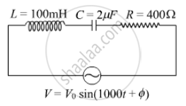
(i) Find the value of the phase difference between the current and the voltage in the series LCR circuit shown below. Which one leads in phase : current or voltage ?
(ii) Without making any other change, find the value of the additional capacitor C1, to be connected in parallel with the capacitor C, in order to make the power factor of the circuit unity.
A coil of resistance 40 Ω is connected across a 4.0 V battery. 0.10 s after the battery is connected, the current in the coil is 63 mA. Find the inductance of the coil.
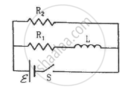
Consider the circuit shown in figure. (a) Find the current through the battery a long time after the switch S is closed. (b) Suppose the switch is again opened at t = 0. What is the time constant of the discharging circuit? (c) Find the current through the inductor after one time constant.
The phase diffn b/w the current and voltage at resonance is
To reduce the resonant frequency in an LCR series circuit with a generator ______.
A series LCR circuit is connected to an ac source. Using the phasor diagram, derive the expression for the impedance of the circuit.
Three students, X, Y and Z performed an experiment for studying the variation of ac with frequency in a series LCR circuit and obtained the graphs as shown below. They all used
- an AC source of the same emf and
- inductance of the same value.

- Who used minimum resistance?
- In which case will the quality Q factor be maximum?
- What did the students conclude about the nature of impedance at resonant frequency (f0)?
- An ideal capacitor is connected across 220 V, 50 Hz, and 220 V, 100 Hz supplies. Find the ratio of current flowing through it in the two cases.
To reduce the resonant frequency in an L-C-R series circuit with a generator ______.
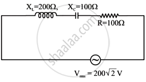
In the given circuit, rms value of current (Irms) through the resistor R is:
Out of the following which one is NOT the characteristic of LCR series resonant circuit?
