Advertisements
Advertisements
Question
In a series LCR circuit, obtain the condition under which watt-less current flows in the circuit ?
Advertisements
Solution
Average power dissipated through a series LCR circuit is given by \[P_{av} = E_v I_v \cos\left( \phi \right)\]
where, Ev = rms value of alternating voltage
Iv = rms value of alternating current
Φ = phase difference between current and voltage
For wattless current, the power dissipated through the circuit should be zero.
\[i . e . , \cos\left( \phi \right) = 0\]
\[ \Rightarrow \phi = \frac{\pi}{2}\]
Hence, the condition for wattless current is that the phase difference between the current and voltage should be π/2 and the circuit is purely inductive or purely capacitive.
APPEARS IN
RELATED QUESTIONS
A series LCR circuit is connected to an ac source. Using the phasor diagram, derive the expression for the impedance of the circuit. Plot a graph to show the variation of current with frequency of the source, explaining the nature of its variation.
Derive an expression for the average power consumed in a series LCR circuit connected to a.c. source in which the phase difference between the voltage and the current in the circuit is Φ.
An LR circuit with emf ε is connected at t = 0. (a) Find the charge Q which flows through the battery during 0 to t. (b) Calculate the work done by the battery during this period. (c) Find the heat developed during this period. (d) Find the magnetic field energy stored in the circuit at time t. (e) Verify that the results in the three parts above are consistent with energy conservation.
The selectivity of a series LCR a.c. circuit is large, when ______.
A series LCR circuit with L = 0.12 H, C = 480 nF, R = 23 Ω is connected to a 230 V variable frequency supply.
(a) What is the source frequency for which current amplitude is maximum. Obtain this maximum value.
(b) What is the source frequency for which average power absorbed by the circuit is maximum. Obtain the value of this maximum power.
(c) For which frequencies of the source is the power transferred to the circuit half the power at resonant frequency? What is the current amplitude at these frequencies?
(d) What is the Q-factor of the given circuit?
If an LCR series circuit is connected to an ac source, then at resonance the voltage across ______.
In an LCR series a.c. circuit, the voltage across each of the components, L, C and R is 50V. The voltage across the LC combination will be ______.
To reduce the resonant frequency in an LCR series circuit with a generator ______.
To reduce the resonant frequency in an L-C-R series circuit with a generator ______.
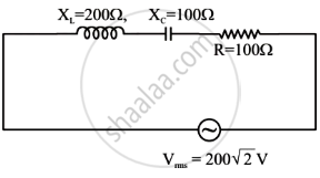
In the given circuit, rms value of current (Irms) through the resistor R is: