Advertisements
Advertisements
प्रश्न
When an alternating voltage of 220V is applied across device X, a current of 0.25A flows which lags behind the applied voltage in phase by π/2 radian. If the same voltage is applied across another device Y, the same current flows but now it is in phase with the applied voltage.
- Name the devices X and Y.
- Calculate the current flowing in the circuit when the same voltage is applied across the series combination of X and Y.
Advertisements
उत्तर
(i) In device X, the Current lags behind the voltage by π/2, X is an inductor.
In device Y, Current in phase with the applied voltage, and Y is resistor.
(ii) We are given that,
Current = `"V"/"X"_"L"`
Or, `0.25 = 220/"X"_"L"`,
∴ XL = 880Ω
Again, Current = `"V"/"R"`
Or, `0.25 = 220/"R"`
∴ R = 880Ω
For the series combination of X and Y,
Equivalent impedance Z = `sqrt(880^2 + 880^2)`
Z = `880sqrt2Omega`
Current = `"V"/"Z"`
Or, I = `220/(880sqrt2)`
∴ I = 0.177 A
APPEARS IN
संबंधित प्रश्न
In a series LCR circuit, VL = VC ≠ VR. What is the value of power factor?
An inductor-coil of resistance 10 Ω and inductance 120 mH is connected across a battery of emf 6 V and internal resistance 2 Ω. Find the charge which flows through the inductor in (a) 10 ms, (b) 20 ms and (c) 100 ms after the connections are made.
An LR circuit with emf ε is connected at t = 0. (a) Find the charge Q which flows through the battery during 0 to t. (b) Calculate the work done by the battery during this period. (c) Find the heat developed during this period. (d) Find the magnetic field energy stored in the circuit at time t. (e) Verify that the results in the three parts above are consistent with energy conservation.
Draw a labelled graph showing a variation of impedance of a series LCR circuit with frequency of the a.c. supply.
Answer the following question.
In a series LCR circuit connected across an ac source of variable frequency, obtain the expression for its impedance and draw a plot showing its variation with frequency of the ac source.
A series LCR circuit with R = 20 Ω, L = 1.5 H and C = 35 µF is connected to a variable-frequency 200 V ac supply. When the frequency of the supply equals the natural frequency of the circuit, what is the average power transferred to the circuit in one complete cycle?
Obtain the resonant frequency and Q-factor of a series LCR circuit with L = 3.0 H, C = 27 µF, and R = 7.4 Ω. It is desired to improve the sharpness of the resonance of the circuit by reducing its ‘full width at half maximum’ by a factor of 2. Suggest a suitable way.
For an LCR circuit driven at frequency ω, the equation reads
`L (di)/(dt) + Ri + q/C = v_i = v_m` sin ωt
- Multiply the equation by i and simplify where possible.
- Interpret each term physically.
- Cast the equation in the form of a conservation of energy statement.
- Integrate the equation over one cycle to find that the phase difference between v and i must be acute.
Draw a labelled graph showing variation of impedance (Z) of a series LCR circuit Vs frequency (f) of the ac supply. Mark the resonant frequency as f0·
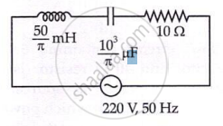
The net impedance of circuit (as shown in figure) will be ______.