Advertisements
Advertisements
प्रश्न
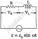
Find the value of t/τ for which the current in an LR circuit builds up to (a) 90%, (b) 99% and (c) 99.9% of the steady-state value.
Advertisements
उत्तर
Current i in the LR circuit at time t is given by
i = i0(1 − e−t/τ)
Here,
i0 = Steady-state value of the current
(a) When the value of the current reaches 90% of the steady-state value:-
\[i = \frac{90}{100} \times i_0\]
\[\frac{90}{100} i_0\] = io(1 − e−t/τ)
⇒ 0.9 = 1 − e−t/τ
⇒ e−t/τ = 0.1
On taking natural logarithm (ln) of both sides, we get
ln (e−t/τ) = ln 0.1
`-t/tau=-2.3`
`rArr t/tau=2.3`
(b) When the value of the current reaches 99% of the steady-state value:-
\[\frac{99}{100} i_0\] = i0(1 − e−t/τ)
e−t/τ = 0.01
On taking natural logarithm (ln) of both sides, we get
ln e−t/τ = ln 0.01
`rArr -t/tau=-4.6`
`rArr t/tau=4.6`
(c) When the value of the current reaches 99.9% of the steady-state value:-
\[\frac{99 . 9}{100} i_0\] = i0(1 − e−t/τ)
⇒ e−t/τ = 0.001
On taking natural logarithm (ln) of both sides, we get
ln e−t/τ = ln 0.001
`rArr -t/tau=-6.9`
`rArr t/tau=6.9`
APPEARS IN
संबंधित प्रश्न
In a series LCR circuit, obtain the condition under which watt-less current flows in the circuit ?
A series LCR circuit is connected to an ac source. Using the phasor diagram, derive the expression for the impedance of the circuit. Plot a graph to show the variation of current with frequency of the source, explaining the nature of its variation.
An L-R circuit has L = 1.0 H and R = 20 Ω. It is connected across an emf of 2.0 V at t = 0. Find di/dt at (a) t = 100 ms, (b) t = 200 ms and (c) t = 1.0 s.
An LR circuit contains an inductor of 500 mH, a resistor of 25.0 Ω and an emf of 5.00 V in series. Find the potential difference across the resistor at t = (a) 20.0 ms, (b) 100 ms and (c) 1.00 s.
(i) An a.c. source of emf ε = 200 sin omegat is connected to a resistor of 50 Ω . calculate :
(1) Average current (`"I"_("avg")`)
(2) Root mean square (rms) value of emf
(ii) State any two characteristics of resonance in an LCR series circuit.
What will be the potential difference in the circuit when direct current is passed through the circuit?
In a series, LCR circuit, obtain an expression for the resonant frequency.
Draw a labelled graph showing a variation of impedance of a series LCR circuit with frequency of the a.c. supply.
Using the phasor diagram, derive the expression for the current flowing in an ideal inductor connected to an a.c. source of voltage, v= vo sin ωt. Hence plot graphs showing the variation of (i) applied voltage and (ii) the current as a function of ωt.
A series LCR circuit with R = 20 Ω, L = 1.5 H and C = 35 µF is connected to a variable-frequency 200 V ac supply. When the frequency of the supply equals the natural frequency of the circuit, what is the average power transferred to the circuit in one complete cycle?
Which of the following components of an LCR circuit, with a.c. supply, dissipates energy?
A series LCR circuit containing a 5.0 H inductor, 80 µF capacitors, and 40 Ω resistor is connected to a 230 V variable frequency ac source. The angular frequencies of the source at which power is transferred to the circuit are half the power at the resonant angular frequency are likely to be ______.
Which of the following combinations should be selected for better tuning of an LCR circuit used for communication?
As the frequency of an ac circuit increases, the current first increases and then decreases. What combination of circuit elements is most likely to comprise the circuit?
- Inductor and capacitor.
- Resistor and inductor.
- Resistor and capacitor.
- Resistor, inductor and capacitor.
For an LCR circuit driven at frequency ω, the equation reads
`L (di)/(dt) + Ri + q/C = v_i = v_m` sin ωt
- Multiply the equation by i and simplify where possible.
- Interpret each term physically.
- Cast the equation in the form of a conservation of energy statement.
- Integrate the equation over one cycle to find that the phase difference between v and i must be acute.
Which of the following statements about a series LCR circuit connected to an ac source is correct?
Three students, X, Y and Z performed an experiment for studying the variation of ac with frequency in a series LCR circuit and obtained the graphs as shown below. They all used
- an AC source of the same emf and
- inductance of the same value.

- Who used minimum resistance?
- In which case will the quality Q factor be maximum?
- What did the students conclude about the nature of impedance at resonant frequency (f0)?
- An ideal capacitor is connected across 220 V, 50 Hz, and 220 V, 100 Hz supplies. Find the ratio of current flowing through it in the two cases.
To an ac power supply of 220 V at 50 Hz, a resistor of 20 Ω, a capacitor of reactance 25 Ω and an inductor of reactance 45 Ω are connected in series. The corresponding current in the circuit and the phase angle between the current and the voltage is respectively:
What is true of the current through the resistor, inductor, and capacitor at every instant?
