Advertisements
Advertisements
Question
An alternating voltage of 220 V is applied across a device X. A current of 0.22 A flows in the circuit and it lags behind the applied voltage in phase by π/2 radian. When the same voltage is applied across another device Y, the current in the circuit remains the same and it is in phase with the applied voltage.
- Name the devices X and Y and,
- Calculate the current flowing in the circuit when the same voltage is applied across the series combination of X and Y.
Advertisements
Solution
- X is a resistor and Y is the capacitor.
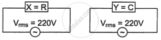
R = `V_{rms}/I_{rms} = 220/0.22 = 1000 Omega`
R = XC = 1000Ω
When R and C are in series.
`I_{rms} = V_{rms}/Z = V_{rms}/sqrt(R^2 + (X_C)^2)`
= `220/sqrt((1000)^2 + (1000)^2)`
= `220/(1000 xx sqrt2)`
`I_{rms} = 0.156` A
APPEARS IN
RELATED QUESTIONS
In a series LCR circuit connected to an a.c. source of voltage v = vmsinωt, use phasor diagram to derive an expression for the current in the circuit. Hence, obtain the expression for the power dissipated in the circuit. Show that power dissipated at resonance is maximum
A source of ac voltage v = v0 sin ωt, is connected across a pure inductor of inductance L. Derive the expressions for the instantaneous current in the circuit. Show that average power dissipated in the circuit is zero.
An ac circuit as shown in the figure has an inductor of inductance L and a resistor or resistance R connected in series. Using the phasor diagram, explain why the voltage in the circuit will lead the current in phase.
Answer the following question.
In a series LCR circuit connected across an ac source of variable frequency, obtain the expression for its impedance and draw a plot showing its variation with frequency of the ac source.
Keeping the source frequency equal to the resonating frequency of the series LCR circuit, if the three elements, L, C and R are arranged in parallel, show that the total current in the parallel LCR circuit is minimum at this frequency. Obtain the current rms value in each branch of the circuit for the elements and source specified for this frequency.
Obtain the resonant frequency and Q-factor of a series LCR circuit with L = 3.0 H, C = 27 µF, and R = 7.4 Ω. It is desired to improve the sharpness of the resonance of the circuit by reducing its ‘full width at half maximum’ by a factor of 2. Suggest a suitable way.
The phase diffn b/w the current and voltage at resonance is
A series RL circuit with R = 10 Ω and L = `(100/pi)` mH is connected to an ac source of voltage V = 141 sin (100 πt), where V is in volts and t is in seconds. Calculate
- the impedance of the circuit
- phase angle, and
- the voltage drop across the inductor.
A series LCR circuit is connected to an ac source. Using the phasor diagram, derive the expression for the impedance of the circuit.
The net impedance of circuit (as shown in figure) will be ______.