Advertisements
Advertisements
Question
In a meter bridge the point D is a neutral point (Figure).
- The meter bridge can have no other neutral point for this set of resistances.
- When the jockey contacts a point on meter wire left of D, current flows to B from the wire.
- When the jockey contacts a point on the meter wire to the right of D, current flows from B to the wire through galvanometer.
- When R is increased, the neutral point shifts to left.
Options
a and c
a and d
b and c
c and d
Advertisements
Solution
a and c
Explanation:
In case of meter bridge, the resistance wire AC is 100 cm long. Varying the position of tapping point B, bridge is balanced. If in balanced position of bridge AB = l, BC = (100 – 1) so that Q/P = (100 – 1)/1. Also P/Q = R/S ⇒ S =(100 – 1)/1R
When there is no deflection in galvanometer there is no current across the galvanometer, then points B and D are at the same potential. That point at which the galvanometer shows no deflection is called the null point and then potential at B and neutral point D is the same. When the jockey contacts a point on the meter wire to the right of D, the potential drop across AD is more than the potential drop across AB, which brings the potential of point D less than that of B, hence current flows from B to D in the galvanometer wire.
APPEARS IN
RELATED QUESTIONS
State the two Kirchhoff’s rules used in electric networks. How are there rules justified?
Given n resistors each of resistance R, how will you combine them to get the (i) maximum (ii) minimum effective resistance? What is the ratio of the maximum to minimum resistance?
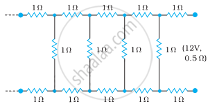
Determine the current drawn from a 12 V supply with internal resistance 0.5 Ω by the infinite network shown in the figure. Each resistor has 1 Ω resistance.
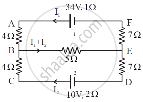
ε1 and ε2 are two batteries having emf of 34V and 10V respectively and internal resistance of 1Ω and 2Ω respectively. They are connected as shown in the figure below. Using Kirchhoff’s Laws of electrical networks, calculate the currents I1 and I2.
Given the resistances of 1 Ω, 2 Ω, 3 Ω, how will be combine them to get an equivalent resistance of (11/5) Ω?
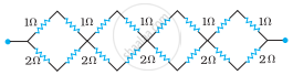
Determine the equivalent resistance of networks shown in Fig.
State Kirchhoff's rules for an electric network. Using Kirchhoff's rules, obtain the balance condition in terms of the resistances of four arms of Wheatstone bridge.
Calculate the value of the resistance R in the circuit shown in the figure so that the current in the circuit is 0.2 A. What would b the potential difference between points B and E?

Consider the following two statements:-
(A) Kirchhoff's junction law follows from conservation of charge.
(B) Kirchhoff's loop law follows from conservative nature of electric field.
Find the circuit in the three resistors shown in the figure.
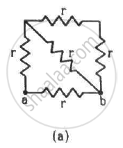
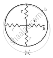
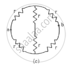
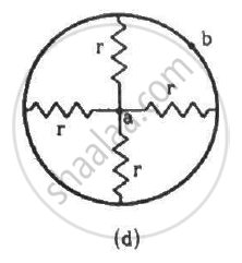
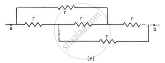
Find the equivalent resistances of the networks shown in the figure between the points a and b.
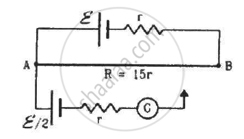
Consider the potentiometer circuit as arranged in the figure. The potentiometer wire is 600 cm long. (a) At what distance from the point A should the jockey touch the wire to get zero deflection in the galvanometer? (b) If the jockey touches the wire at a distance of 560 cm from A, what will be the current in the galvanometer?
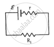
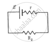
Two unequal resistances, R1 and R2, are connected across two identical batteries of emf ε and internal resistance r (see the figure). Can the thermal energies developed in R1 and R2 be equal in a given time? If yes, what will be the condition?
In the circuit shown in the figure below, E1 and E2 are two cells having emfs 2 V and 3 V respectively, and negligible internal resistance. Applying Kirchhoff’s laws of electrical networks, find the values of currents l1 and I2.

Solve the following question.
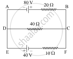
Using Kirchhoff’s rules, calculate the current through the 40 Ω and 20 Ω resistors in the following circuit.
State Kirchhoff’s current rule.
State Kirchhoff ’s voltage rule.
State the principle of potentiometer.
Obtain the condition for bridge balance in Wheatstone’s bridge.
How the emf of two cells are compared using potentiometer?
Lightning is a very good example of a natural current. In typical lightning, there is 109 J energy transfer across the potential difference of 5 × 10⁷ V during a time interval of 0.2 s. Using this information, estimate the following quantities:
- the total amount of charge transferred between cloud and ground
- the current in the lightning bolt
- the power delivered in 0.2 s.
In a potentiometer arrangement, a cell of emf 1.25 V gives a balance point at 35 cm length of the wire. If the cell is replaced by another cell and the balance point shifts to 63 cm, what is the emf of the second cell?
Kirchhoff’s second law is a consequence of law of conservation of ______.
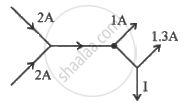
Figure shows current in a part of an electrical circuit. Then current I is ______.

While measuring the length of the rod by vernier callipers, the reading on the main scale is 6.4 cm and the eight divisions on vernier is in line with marking on the main scale division. If the least count of callipers is 0.01 and zero error - 0.04 cm, the length of the rod is ______.
The e.m.f of The battery in a thermocouple is doubled. The rate of heat generated at one of the junction will.
The figure below shows current in a part of electric circuit. The current I is ______.
Three resistors having resistances r1, r2 and r3 are connected as shown in the given circuit. The ratio `i_3/i_1` of currents in terms of resistances used in the circuit is:
The circuit in figure shows two cells connected in opposition to each other. Cell E1 is of emf 6V and internal resistance 2Ω; the cell E2 is of emf 4V and internal resistance 8Ω. Find the potential difference between the points A and B.
Two cells of voltage 10V and 2V and internal resistances 10Ω and 5Ω respectively, are connected in parallel with the positive end of 10V battery connected to negative pole of 2V battery (Figure). Find the effective voltage and effective resistance of the combination.

State the two Kirchhoff’s rules used in the analysis of electric circuits and explain them.
In the circuit shown in Figure below, E1 and E2 are batteries having emfs of 25V and 26V. They have an internal resistance of 1 Ω and 5 Ω respectively. Applying Kirchhoff’s laws of electrical networks, calculate the currents I1 and I2.

The figure below shows two batteries, E1 and E2, having emfs of 18V and 10V and internal resistances of 1 Ω and 2 Ω, respectively. W1, W2 and W3 are uniform metallic wires AC, FD and BE having resistances of 8 Ω, 6 Ω and 10 Ω respectively. B and E are midpoints of the wires W1 and W2. Using Kirchhoff's laws of electrical circuits, calculate the current flowing in the wire W3:

