Advertisements
Advertisements
Question
It is required to construct a 10 µF capacitor which can be connected across a 200 V battery. Capacitors of capacitance 10 µF are available but they can withstand only 50 V. Design a combination which can yield the desired result.
Advertisements
Solution
Let the number of capacitors in series (connected in a row) be x.
The maximum voltage that the capacitors can withstand is 50 V.
The voltage across each row should be equal to 200 V.
Therefore,
x × 50 = 200
Thus,
x = 4 capacitors
Now,
Let there be y such rows.
So, the equivalent capacitance of the combination will be xy.
⇒ xy = 10
⇒ y = 10 x = 4 capacitors
Thus, to yield the required result, the combination of 4 rows, each of 4 capacitors having capacitance 10 µF and breakdown voltage 50 V, is required.
APPEARS IN
RELATED QUESTIONS
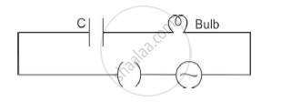
A bulb is connected in series with a variable capacitor and an AC source as shown. What happens to the brightness of the bulb when the key is plugged in and capacitance of the capacitor is gradually reduced?
A capacitor of capacitance ‘C’ is charged to ‘V’ volts by a battery. After some time the battery is disconnected and the distance between the plates is doubled. Now a slab of dielectric constant, 1 < k < 2, is introduced to fill the space between the plates. How will the following be affected? (a) The electric field between the plates of the capacitor Justify your answer by writing the necessary expressions.
A capacitor of capacitance ‘C’ is charged to ‘V’ volts by a battery. After some time the battery is disconnected and the distance between the plates is doubled. Now a slab of dielectric constant, 1 < k < 2, is introduced to fill the space between the plates. How will the following be affected? (b) The energy stored in the capacitor Justify your answer by writing the necessary expressions
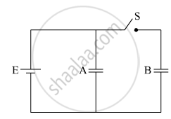
Two identical parallel plate capacitors A and B are connected to a battery of V volts with the switch S closed. The switch is now opened and the free space between the plates of the capacitors is filled with a dielectric of dielectric constant K. Find the ratio of the total electrostatic energy stored in both capacitors before and after the introduction of the dielectric.
As `C = (1/V) Q` , can you say that the capacitance C is proportional to the charge Q?
A capacitor of capacitance C is charged to a potential V. The flux of the electric field through a closed surface enclosing the capacitor is
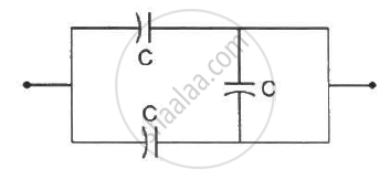
The equivalent capacitance of the combination shown in the figure is _________ .
Two metal spheres of capacitance C1 and C2 carry some charges. They are put in contact and then separated. The final charges Q1 and Q2 on them will satisfy
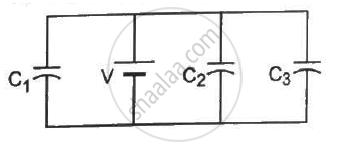
Find the charges on the three capacitors connected to a battery as shown in figure.
Take `C_1 = 2.0 uF , C_2 = 4.0 uF , C_3 = 6.0 uF and V` = 12 volts.
Find the equivalent capacitances of the combinations shown in figure between the indicated points.
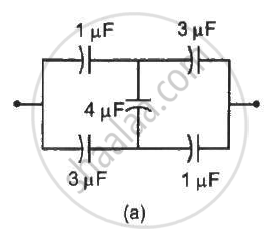
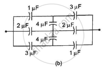
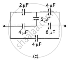
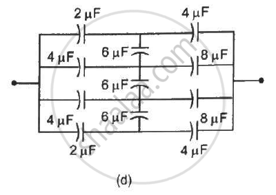
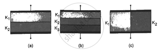
Find the capacitances of the capacitors shown in figure . The plate area is Aand the separation between the plates is d. Different dielectric slabs in a particular part of the figure are of the same thickness and the entire gap between the plates is filled with the dielectric slabs.
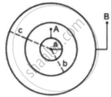
Suppose the space between the two inner shells is filled with a dielectric of dielectric constant K. Find the capacitance of the system between A and B.
Obtain the expression for capacitance for a parallel plate capacitor.
A capacitor is charged by a battery. The battery is removed and another identical uncharged capacitor is connected in parallel. The total electrostatic energy of resulting system ______.
Dielectric constant for a metal is ______.
Between the plates of parallel plate condenser there is 1 mm thick medium shoot of dielectric constant 4. It is charged at 100 volt. The electric field in volt/meter between the plates of capacitor is ______.
Two spherical conductors of capacities 4 µF and 3 µF are charged to same potential having radii 4 cm and 3 cm respectively. If ‘σ1’ and ‘σ2’ represent surface density of charge on respective conductors then ______.
What is the SI unit of capacitance?
Which units are capacitors commonly measured in practice?
