Advertisements
Advertisements
प्रश्न
It is required to construct a 10 µF capacitor which can be connected across a 200 V battery. Capacitors of capacitance 10 µF are available but they can withstand only 50 V. Design a combination which can yield the desired result.
Advertisements
उत्तर
Let the number of capacitors in series (connected in a row) be x.
The maximum voltage that the capacitors can withstand is 50 V.
The voltage across each row should be equal to 200 V.
Therefore,
x × 50 = 200
Thus,
x = 4 capacitors
Now,
Let there be y such rows.
So, the equivalent capacitance of the combination will be xy.
⇒ xy = 10
⇒ y = 10 x = 4 capacitors
Thus, to yield the required result, the combination of 4 rows, each of 4 capacitors having capacitance 10 µF and breakdown voltage 50 V, is required.
APPEARS IN
संबंधित प्रश्न
A capacitor of capacitance ‘C’ is charged to ‘V’ volts by a battery. After some time the battery is disconnected and the distance between the plates is doubled. Now a slab of dielectric constant, 1 < k < 2, is introduced to fill the space between the plates. How will the following be affected? (a) The electric field between the plates of the capacitor Justify your answer by writing the necessary expressions.
Two identical capacitors of 12 pF each are connected in series across a battery of 50 V. How much electrostatic energy is stored in the combination? If these were connected in parallel across the same battery, how much energy will be stored in the combination now?
Also find the charge drawn from the battery in each case.
A capacitor of capacitance ‘C’ is being charged by connecting it across a dc source along with an ammeter. Will the ammeter show a momentary deflection during the process of charging? If so, how would you explain this momentary deflection and the resulting continuity of current in the circuit? Write the expression for the current inside the capacitor.
The plates of a parallel-plate capacitor are made of circular discs of radii 5⋅0 cm each. If the separation between the plates is 1⋅0 mm, what is the capacitance?
A parallel-plate capacitor has plate area 25⋅0 cm2 and a separation of 2⋅00 mm between the plates. The capacitor is connected to a battery of 12⋅0 V. (a) Find the charge on the capacitor. (b) The plate separation is decreased to 1⋅00 mm. Find the extra charge given by the battery to the positive plate.
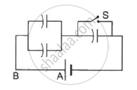
Each capacitor shown in figure has a capacitance of 5⋅0 µF. The emf of the battery is 50 V. How much charge will flow through AB if the switch S is closed?
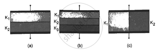
Find the capacitances of the capacitors shown in figure . The plate area is Aand the separation between the plates is d. Different dielectric slabs in a particular part of the figure are of the same thickness and the entire gap between the plates is filled with the dielectric slabs.
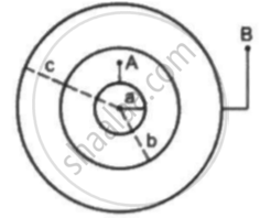
Consider an assembly of three conducting concentric spherical shell of radii a, b and c as shown in figure Find the capacitance of the assembly between the points Aand B.
Three capacitors C1 = 3μF, C2 = 6μF, and C3 = 10μF are connected to a 50 V battery as shown in Figure below:

Calculate:
(i) The equivalent capacitance of the circuit between points A and B.
(ii) The charge on C1.
The variation of inductive reactance (XL) of an inductor with the frequency (f) of the ac source of 100 V and variable frequency is shown in fig.
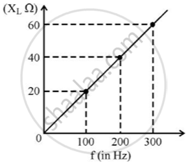
- Calculate the self-inductance of the inductor.
- When this inductor is used in series with a capacitor of unknown value and a resistor of 10 Ω at 300 s–1, maximum power dissipation occurs in the circuit. Calculate the capacitance of the capacitor.
Define ‘capacitance’. Give its unit.
The work done in placing a charge of 8 × 10–18 coulomb on a condenser of capacity 100 micro-farad is ______.
Three capacitors 2µF, 3µF, and 6µF are joined in series with each other. The equivalent capacitance is ____________.
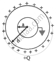
Two spherical conductors A and B of radii a and b(b > a) are placed concentrically in the air. B is given a charge +Q and A is earthed. The equivalent capacitance of the system is ______.
A parallel plate capacitor (A) of capacitance C is charged by a battery to voltage V. The battery is disconnected and an uncharged capacitor (B) of capacitance 2C is connected across A. Find the ratio of final charges on A and B.
Calculate equivalent capacitance of the circuit shown in the Figure given below:

The plates of a parallel plate capacitor are separated by d. Two slabs of different dielectric constant K1 and K2 with thickness `3/8 d and d/2`, respectively, are inserted in the capacitor. Due to this, the capacitance becomes two times larger than when there is nothing between the plates. If K1 = 1.25 K, the value of K1 is:
Eight drops of mercury of equal radius and possessing equal charge combine to form a big drop. The capacitance of bigger drop as compared to each small drop is ______.
Which system is called a capacitor?
Which combination has charge as its constant quantity and potential difference as its variable quantity?
