Advertisements
Advertisements
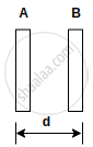
प्रश्न
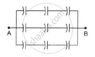
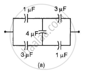
Each of the capacitors shown in figure has a capacitance of 2 µF. find the equivalent capacitance of the assembly between the points A and B. Suppose, a battery of emf 60 volts is connected between A and B. Find the potential difference appearing on the individual capacitors.
Advertisements
उत्तर
There are three rows of capacitors connected in parallel in the given system. In each row, three capacitors of capacitance 2 μF are connected in series.
For each row, the equivalent capacitance is given by
`1/C_r = 1/2 + 1/2 + 1/2`
`⇒ C_r = 2/3 "uF"`
As three rows are connected in parallel, their equivalent capacitance is given by
`C_(eq) = C_r + C_r + C_r = 2/3 + 2/3 + 2/3 = 2 "uF"`
The voltage across each row is the same and is equal to 60 V.
As all capacitors have the same capacitance in each row, the potential difference across their plates is the same.
∴ Potential difference across each capacitor = 20 V
APPEARS IN
संबंधित प्रश्न
A capacitor of capacitance ‘C’ is charged to ‘V’ volts by a battery. After some time the battery is disconnected and the distance between the plates is doubled. Now a slab of dielectric constant, 1 < k < 2, is introduced to fill the space between the plates. How will the following be affected? (a) The electric field between the plates of the capacitor Justify your answer by writing the necessary expressions.
Two identical parallel plate capacitors A and B are connected to a battery of V volts with the switch S closed. The switch is now opened and the free space between the plates of the capacitors is filled with a dielectric of dielectric constant K. Find the ratio of the total electrostatic energy stored in both capacitors before and after the introduction of the dielectric.
The plates of a parallel-plate capacitor are made of circular discs of radii 5⋅0 cm each. If the separation between the plates is 1⋅0 mm, what is the capacitance?
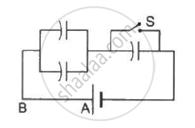
It is required to construct a 10 µF capacitor which can be connected across a 200 V battery. Capacitors of capacitance 10 µF are available but they can withstand only 50 V. Design a combination which can yield the desired result.
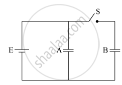
Each capacitor shown in figure has a capacitance of 5⋅0 µF. The emf of the battery is 50 V. How much charge will flow through AB if the switch S is closed?
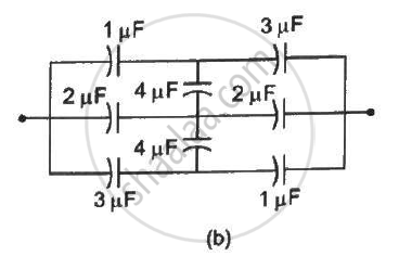
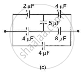
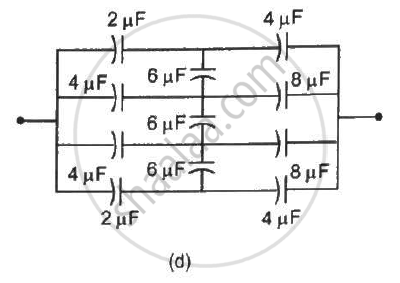
Find the equivalent capacitances of the combinations shown in figure between the indicated points.
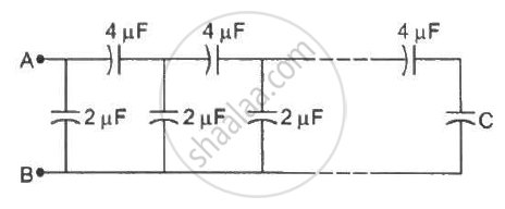
A finite ladder is constructed by connecting several sections of 2 µF, 4 µF capacitor combinations as shown in the figure. It is terminated by a capacitor of capacitance C. What value should be chosen for C, such that the equivalent capacitance of the ladder between the points A and B becomes independent of the number of sections in between?
The separation between the plates of a parallel-plate capacitor is 0⋅500 cm and its plate area is 100 cm2. A 0⋅400 cm thick metal plate is inserted into the gap with its faces parallel to the plates. Show that the capacitance of the assembly is independent of the position of the metal plate within the gap and find its value.
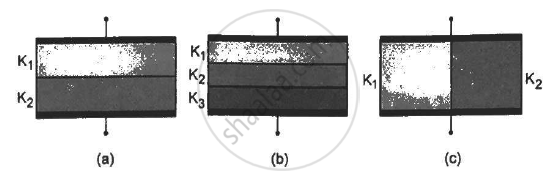
Find the capacitances of the capacitors shown in figure . The plate area is Aand the separation between the plates is d. Different dielectric slabs in a particular part of the figure are of the same thickness and the entire gap between the plates is filled with the dielectric slabs.
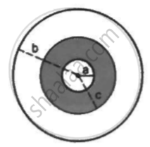
A sphercial capacitor is made of two conducting spherical shells of radii a and b. The space between the shells is filled with a dielectric of dielectric constant K up to a radius c as shown in figure . Calculate the capacitance.
An air-filled parallel-plate capacitor is to be constructed which can store 12 µC of charge when operated at 1200 V. What can be the minimum plate area of the capacitor? The dielectric strength of air is `3 xx 10^6 "Vm"^-1`
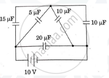
The figure show a network of five capacitors connected to a 10V battery. Calculate the charge acquired by the 5μF capacitor.
Three capacitors C1 = 3μF, C2 = 6μF, and C3 = 10μF are connected to a 50 V battery as shown in Figure below:

Calculate:
(i) The equivalent capacitance of the circuit between points A and B.
(ii) The charge on C1.
Obtain an expression for equivalent capacitance when three capacitors C1, C2 and C3 are connected in series.
Explain in detail the effect of a dielectric placed in a parallel plate capacitor.
The work done in placing a charge of 8 × 10–18 coulomb on a condenser of capacity 100 micro-farad is ______.
Dielectric constant for a metal is ______.
Two plates A and B of a parallel plate capacitor are arranged in such a way, that the area of each plate is S = 5 × 10⁻³ m 2 and distance between them is d = 8.85 mm. Plate A has a positive charge q1 = 10-10 C and Plate B has charge q2 = + 2 × 10⁻¹⁰ C. Then the charge induced on the plate B due to the plate A be - (....... × 10-11 )C
Current versus time and voltage versus time graphs of a circuit element are shown in figure.
 |
 |
The type of the circuit element is ______.
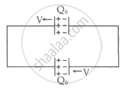
Two identical capacitors are connected as shown and have an initial charge of Q0. The separation between the plates of each capacitor is d0. Suddenly the left plate of the upper capacitor and right plate of the lower capacitor start moving with speed v towards the left while the other plate of each capacitor remains fixed. `("given" (Q_0V)/(2d_0) = 10 A)`. The value of current in the circuit is ______ A.