Advertisements
Advertisements
Question
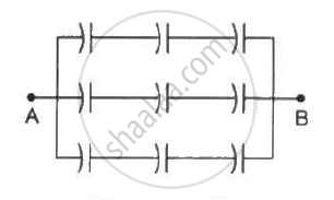
Each of the capacitors shown in figure has a capacitance of 2 µF. find the equivalent capacitance of the assembly between the points A and B. Suppose, a battery of emf 60 volts is connected between A and B. Find the potential difference appearing on the individual capacitors.
Advertisements
Solution
There are three rows of capacitors connected in parallel in the given system. In each row, three capacitors of capacitance 2 μF are connected in series.
For each row, the equivalent capacitance is given by
`1/C_r = 1/2 + 1/2 + 1/2`
`⇒ C_r = 2/3 "uF"`
As three rows are connected in parallel, their equivalent capacitance is given by
`C_(eq) = C_r + C_r + C_r = 2/3 + 2/3 + 2/3 = 2 "uF"`
The voltage across each row is the same and is equal to 60 V.
As all capacitors have the same capacitance in each row, the potential difference across their plates is the same.
∴ Potential difference across each capacitor = 20 V
APPEARS IN
RELATED QUESTIONS
A capacitor of capacitance ‘C’ is charged to ‘V’ volts by a battery. After some time the battery is disconnected and the distance between the plates is doubled. Now a slab of dielectric constant, 1 < k < 2, is introduced to fill the space between the plates. How will the following be affected? (a) The electric field between the plates of the capacitor Justify your answer by writing the necessary expressions.
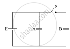
Two identical parallel plate capacitors A and B are connected to a battery of V volts with the switch S closed. The switch is now opened and the free space between the plates of the capacitors is filled with a dielectric of dielectric constant K. Find the ratio of the total electrostatic energy stored in both capacitors before and after the introduction of the dielectric.
Three identical capacitors C1, C2 and C3 of capacitance 6 μF each are connected to a 12 V battery as shown.
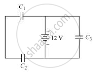
Find
(i) charge on each capacitor
(ii) equivalent capacitance of the network
(iii) energy stored in the network of capacitors
Three capacitors of capacitances 6 µF each are available. The minimum and maximum capacitances, which may be obtained are
The capacitance of a capacitor does not depend on
The plates of a parallel-plate capacitor are made of circular discs of radii 5⋅0 cm each. If the separation between the plates is 1⋅0 mm, what is the capacitance?
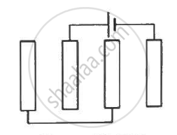
Each of the plates shown in figure has surface area `(96/∈_0) xx 10^-12` Fm on one side and the separation between the consecutive plates is 4⋅0 mm. The emf of the battery connected is 10 volts. Find the magnitude of the charge supplied by the battery to each of the plates connected to it.
The separation between the plates of a parallel-plate capacitor is 0⋅500 cm and its plate area is 100 cm2. A 0⋅400 cm thick metal plate is inserted into the gap with its faces parallel to the plates. Show that the capacitance of the assembly is independent of the position of the metal plate within the gap and find its value.
A parallel-plate capacitor has plate area 100 cm2 and plate separation 1⋅0 cm. A glass plate (dielectric constant 6⋅0) of thickness 6⋅0 mm and an ebonite plate (dielectric constant 4⋅0) are inserted one over the other to fill the space between the plates of the capacitor. Find the new capacitance.
If the voltage applied on a capacitor is increased from V to 2V, choose the correct conclusion.
A capacitor is charged by a battery. The battery is removed and another identical uncharged capacitor is connected in parallel. The total electrostatic energy of resulting system ______.
The positive terminal of 12 V battery is connected to the ground. Then the negative terminal will be at ______.
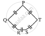
Five capacitor each of capacitance value C are connected as shown in the figure. The ratio of capacitance between P to R, and the capacitance between P and Q is ______.
The radius of a sphere of capacity 1 microfarad in the air is ______
Can the potential function have a maximum or minimum in free space?
A capacitor of capacity 2 µF is charged to a potential difference of 12 V. It is then connected across an inductor of inductance 0.6 mH. The current in the circuit at a time when the potential difference across the capacitor is 6.0 V is ______ × 10-1A.
A capacitor has charge 50 µC. When the gap between the plate is filled with glass wool, then 120 µC charge flows through the battery to capacitor. The dielectric constant of glass wool is ______.
