Advertisements
Advertisements
Question
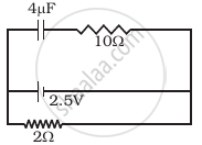
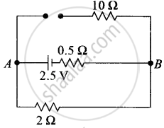
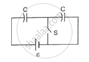
A capacitor of 4 µ F is connected as shown in the circuit (Figure). The internal resistance of the battery is 0.5 Ω. The amount of charge on the capacitor plates will be ______.
Options
0
4 µ C
16 µ C
8 µ C
Advertisements
Solution
A capacitor of 4 µ F is connected as shown in the circuit (Figure). The internal resistance of the battery is 0.5 Ω. The amount of charge on the capacitor plates will be 8 µ C.
Explanation:
A capacitor offers zero resistance in a circuit when it is uncharged, i.e., it can be assumed as short-circuited and it offers infinite resistance when it is fully charged.
At steady state
At steady state the capacitor offers infinite resistance in the DC circuit and acts as the open circuit as shown in the figure, therefore no current flows through the capacitor and 10 Ω resistance, leaving zero potential difference across 10 Ω resistance. Hence potential difference across capacitors will be the potential difference across A and B.
The potential difference across lower and middle branches of the circuit is equal to the potential difference across the capacitor of upper branch of circuit.
Current flows through 2 Ω resistance from left to right, is given by I = v/R + r = 1A.The potential difference across 2 Ω resistance, V = IR = 1 × 2 = 2V Hence potential difference across capacitors is also 2V.
The charge on capacitor is q = CV = (2 μ F) × 2V = 8 μ C.
APPEARS IN
RELATED QUESTIONS
A capacitor of capacitance C is charged fully by connecting it to a battery of emf E. It is then disconnected from the battery. If the separation between the plates of the capacitor is now doubled, how will the following change?
(i) charge stored by the capacitor.
(ii) Field strength between the plates.
(iii) Energy stored by the capacitor.
Justify your answer in each case.
A capacitor of capacitance ‘C’ is charged to ‘V’ volts by a battery. After some time the battery is disconnected and the distance between the plates is doubled. Now a slab of dielectric constant, 1 < k < 2, is introduced to fill the space between the plates. How will the following be affected? (b) The energy stored in the capacitor Justify your answer by writing the necessary expressions
The capacitance of a capacitor does not depend on
Suppose, one wishes to construct a 1⋅0 farad capacitor using circular discs. If the separation between the discs be kept at 1⋅0 mm, what would be the radius of the discs?
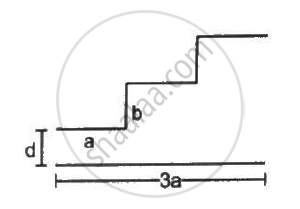
A capacitor is made of a flat plate of area A and a second plate having a stair-like structure as shown in figure . The width of each stair is a and the height is b. Find the capacitance of the assembly.
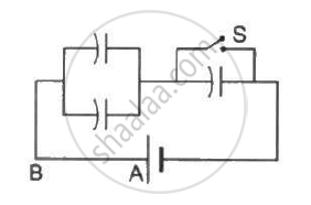
Each capacitor shown in figure has a capacitance of 5⋅0 µF. The emf of the battery is 50 V. How much charge will flow through AB if the switch S is closed?
Consider the situation shown in the figure. The switch S is open for a long time and then closed. (a) Find the charge flown through the battery when the switch S is closed. (b) Find the work done by the battery.(c) Find the change in energy stored in the capacitors.(d) Find the heat developed in the system.
A 5⋅0 µF capacitor is charged to 12 V. The positive plate of this capacitor is now connected to the negative terminal of a 12 V battery and vice versa. Calculate the heat developed in the connecting wires.
A parallel-plate capacitor of plate area A and plate separation d is charged to a potential difference V and then the battery is disconnected. A slab of dielectric constant K is then inserted between the plates of the capacitor so as to fill the space between the plates. Find the work done on the system in the process of inserting the slab.
A sphercial capacitor is made of two conducting spherical shells of radii a and b. The space between the shells is filled with a dielectric of dielectric constant K up to a radius c as shown in figure . Calculate the capacitance.
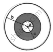
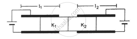
Figure shows two parallel plate capacitors with fixed plates and connected to two batteries. The separation between the plates is the same for the two capacitors. The plates are rectangular in shape with width b and lengths l1 and l2. The left half of the dielectric slab has a dielectric constant K1 and the right half K2. Neglecting any friction, find the ration of the emf of the left battery to that of the right battery for which the dielectric slab may remain in equilibrium.
Obtain the expression for capacitance for a parallel plate capacitor.
Two similar conducting spheres having charge+ q and -q are placed at 'd' seperation from each other in air. The radius of each ball is r and the separation between their centre is d (d >> r). Calculate the capacitance of the two ball system ______.

For changing the capacitance of a given parallel plate capacitor, a dielectric material of dielectric constant K is used, which has the same area as the plates of the capacitor.
The thickness of the dielectric slab is `3/4`d, where 'd' is the separation between the plate of the parallel plate capacitor.
The new capacitance (C') in terms of the original capacitance (C0) is given by the following relation:
A 5µF capacitor is charged fully by a 220 V supply. It is then disconnected from the supply and is connected in series to another uncharged 2.5 µF capacitor If the energy change during the charge redistribution is `"X"/100`J then value of X to the 100 nearest integer is ______.
A parallel plate capacitor (A) of capacitance C is charged by a battery to voltage V. The battery is disconnected and an uncharged capacitor (B) of capacitance 2C is connected across A. Find the ratio of final charges on A and B.
The plates of a parallel plate capacitor are separated by d. Two slabs of different dielectric constant K1 and K2 with thickness `3/8 d and d/2`, respectively, are inserted in the capacitor. Due to this, the capacitance becomes two times larger than when there is nothing between the plates. If K1 = 1.25 K, the value of K1 is:
