Advertisements
Advertisements
प्रश्न
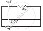
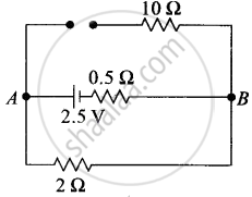
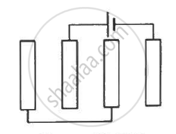
A capacitor of 4 µ F is connected as shown in the circuit (Figure). The internal resistance of the battery is 0.5 Ω. The amount of charge on the capacitor plates will be ______.
पर्याय
0
4 µ C
16 µ C
8 µ C
Advertisements
उत्तर
A capacitor of 4 µ F is connected as shown in the circuit (Figure). The internal resistance of the battery is 0.5 Ω. The amount of charge on the capacitor plates will be 8 µ C.
Explanation:
A capacitor offers zero resistance in a circuit when it is uncharged, i.e., it can be assumed as short-circuited and it offers infinite resistance when it is fully charged.
At steady state
At steady state the capacitor offers infinite resistance in the DC circuit and acts as the open circuit as shown in the figure, therefore no current flows through the capacitor and 10 Ω resistance, leaving zero potential difference across 10 Ω resistance. Hence potential difference across capacitors will be the potential difference across A and B.
The potential difference across lower and middle branches of the circuit is equal to the potential difference across the capacitor of upper branch of circuit.
Current flows through 2 Ω resistance from left to right, is given by I = v/R + r = 1A.The potential difference across 2 Ω resistance, V = IR = 1 × 2 = 2V Hence potential difference across capacitors is also 2V.
The charge on capacitor is q = CV = (2 μ F) × 2V = 8 μ C.
APPEARS IN
संबंधित प्रश्न
A capacitor of capacitance ‘C’ is charged to ‘V’ volts by a battery. After some time the battery is disconnected and the distance between the plates is doubled. Now a slab of dielectric constant, 1 < k < 2, is introduced to fill the space between the plates. How will the following be affected? (a) The electric field between the plates of the capacitor Justify your answer by writing the necessary expressions.
A capacitor of capacitance ‘C’ is charged to ‘V’ volts by a battery. After some time the battery is disconnected and the distance between the plates is doubled. Now a slab of dielectric constant, 1 < k < 2, is introduced to fill the space between the plates. How will the following be affected? (b) The energy stored in the capacitor Justify your answer by writing the necessary expressions
A parallel plate capacitor of capacitance C is charged to a potential V. It is then connected to another uncharged capacitor having the same capacitance. Find out the ratio of the energy stored in the combined system to that stored initially in the single capacitor.
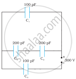
Obtain the equivalent capacitance of the network in Figure. For a 300 V supply, determine the charge and voltage across each capacitor.
A parallel-plate capacitor has plate area 25⋅0 cm2 and a separation of 2⋅00 mm between the plates. The capacitor is connected to a battery of 12⋅0 V. (a) Find the charge on the capacitor. (b) The plate separation is decreased to 1⋅00 mm. Find the extra charge given by the battery to the positive plate.
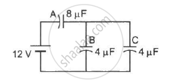
Find the charge appearing on each of the three capacitors shown in figure .
Each of the plates shown in figure has surface area `(96/∈_0) xx 10^-12` Fm on one side and the separation between the consecutive plates is 4⋅0 mm. The emf of the battery connected is 10 volts. Find the magnitude of the charge supplied by the battery to each of the plates connected to it.
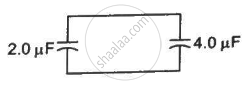
A capacitor of capacitance 2⋅0 µF is charged to a potential difference of 12 V. It is then connected to an uncharged capacitor of capacitance 4⋅0 µF as shown in figure . Find (a) the charge on each of the two capacitors after the connection, (b) the electrostatic energy stored in each of the two capacitors and (c) the heat produced during the charge transfer from one capacitor to the other.
An air-filled parallel-plate capacitor is to be constructed which can store 12 µC of charge when operated at 1200 V. What can be the minimum plate area of the capacitor? The dielectric strength of air is `3 xx 10^6 "Vm"^-1`
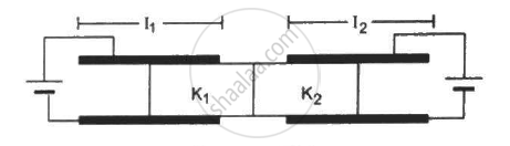
Figure shows two parallel plate capacitors with fixed plates and connected to two batteries. The separation between the plates is the same for the two capacitors. The plates are rectangular in shape with width b and lengths l1 and l2. The left half of the dielectric slab has a dielectric constant K1 and the right half K2. Neglecting any friction, find the ration of the emf of the left battery to that of the right battery for which the dielectric slab may remain in equilibrium.
Three capacitors C1 = 3μF, C2 = 6μF, and C3 = 10μF are connected to a 50 V battery as shown in Figure below:

Calculate:
(i) The equivalent capacitance of the circuit between points A and B.
(ii) The charge on C1.
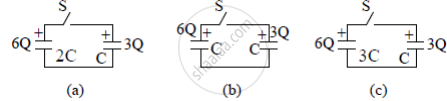
Three circuits, each consisting of a switch 'S' and two capacitors, are initially charged, as shown in the figure. After the switch has been closed, in which circuit will the charge on the left-hand capacitor
(i) increase,
(ii) decrease, and
(iii) remains the same? Give reasons.
If the voltage applied on a capacitor is increased from V to 2V, choose the correct conclusion.
Explain in detail the effect of a dielectric placed in a parallel plate capacitor.
The capacitance of a parallel plate capacitor is 60 µF. If the distance between the plates is tripled and area doubled then new capacitance will be ______.
A parallel plate capacitor is filled by a dielectric whose relative permittivity varies with the applied voltage (U) as ε = αU where α = 2V–1. A similar capacitor with no dielectric is charged to U0 = 78V. It is then connected to the uncharged capacitor with the dielectric. Find the final voltage on the capacitors.
The plates of a parallel plate capacitor are separated by d. Two slabs of different dielectric constant K1 and K2 with thickness `3/8 d and d/2`, respectively, are inserted in the capacitor. Due to this, the capacitance becomes two times larger than when there is nothing between the plates. If K1 = 1.25 K, the value of K1 is:
