Advertisements
Advertisements
प्रश्न
When 1⋅0 × 1012 electrons are transferred from one conductor to another, a potential difference of 10 V appears between the conductors. Calculate the capacitance of the two-conductor system.
Advertisements
उत्तर
As 1.0 × 10¹² electrons are transferred from one conductor to another, the conductor to which the electrons are transferred becomes negatively charged and the other conductor becomes positively charged.
Now ,
Magnitude of the net charge on each conductor, `Q = (1.0 xx 10^12) xx (1.6 xx 10^-19) C = 1.6 xx 10^-7 C`
Magnitude of the potential difference between the conductors, V = 10 V
The capacitance C is the ratio of the magnitude of the charge on either conductor to the magnitude of the potential difference between the conductors.
`C = Q/V`
⇒ `C = (1.6 xx 10^-7)/10 = 1.6 xx 10^-8 F`
Hence, the value of the capacitance of the given two conductor systems is `1.6 xx 10^-8 F` .
APPEARS IN
संबंधित प्रश्न
A capacitor of capacitance ‘C’ is being charged by connecting it across a dc source along with an ammeter. Will the ammeter show a momentary deflection during the process of charging? If so, how would you explain this momentary deflection and the resulting continuity of current in the circuit? Write the expression for the current inside the capacitor.
The capacitance of a capacitor does not depend on
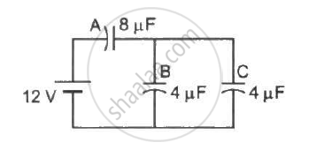
Find the charge appearing on each of the three capacitors shown in figure .
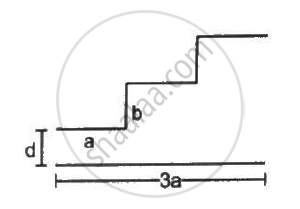
A capacitor is made of a flat plate of area A and a second plate having a stair-like structure as shown in figure . The width of each stair is a and the height is b. Find the capacitance of the assembly.
A capacitor of capacitance 10 μF is connected to a battery of emf 2 V. It is found that it takes 50 ms for the charge of the capacitor to become 12.6 μC. Find the resistance of the circuit.
The separation between the plates of a parallel-plate capacitor is 0⋅500 cm and its plate area is 100 cm2. A 0⋅400 cm thick metal plate is inserted into the gap with its faces parallel to the plates. Show that the capacitance of the assembly is independent of the position of the metal plate within the gap and find its value.
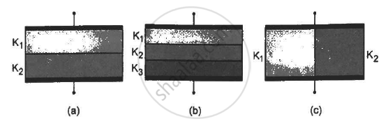
Find the capacitances of the capacitors shown in figure . The plate area is Aand the separation between the plates is d. Different dielectric slabs in a particular part of the figure are of the same thickness and the entire gap between the plates is filled with the dielectric slabs.
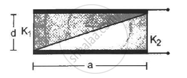
A capacitor is formed by two square metal-plates of edge a, separated by a distance d. Dielectrics of dielectric constant K1 and K2 are filled in the gap as shown in figure . Find the capacitance.
Derive the expression for resultant capacitance, when the capacitor is connected in series.
A capacitor is charged by a battery. The battery is removed and another identical uncharged capacitor is connected in parallel. The total electrostatic energy of resulting system ______.
- Charge on each capacitor remains same and equals to the main charge supplied by the battery.
- Potential difference and energy distribute in the reverse ratio of capacitance.
- Effective capacitance is even les than the least of teh individual capacitances.
The radius of a sphere of capacity 1 microfarad in the air is ______
The displacement current of 4.425 µA is developed in the space between the plates of the parallel plate capacitor when voltage is changing at a rate of 106 Vs-1. The area of each plate of the capacitor is 40 cm2. The distance between each plate of the capacitor is x × 10-3 m. The value of x is ______.
(Permittivity of free space, ε0 = 8.85 × 10⁻¹²C2N-1m-2).
A leaky parallel plate capacitor is filled completely with a material having dielectric constant K = 5 and electric conductivity σ = 7.4 × 10⁻¹² Ω-1 m-1. If the charge on the plate at the instant t = 0 is q = 8.85 µC, then the leakage current at the instant t = 12 s is ______ × 10-1 µA.
A capacitor of capacity 2 µF is charged to a potential difference of 12 V. It is then connected across an inductor of inductance 0.6 mH. The current in the circuit at a time when the potential difference across the capacitor is 6.0 V is ______ × 10-1A.
Current versus time and voltage versus time graphs of a circuit element are shown in figure.
 |
 |
The type of the circuit element is ______.
In a series combination, which quantity is the same on each capacitor?
In a parallel combination, which quantity is the same across each capacitor?
