Definitions [14]
Electromotive force (e) is the energy provided by a cell or battery per coulomb of charge passing through it.
\[e=\frac{E}{Q}\]
It is measured in volt (V).
The resistance offered by the electrolyte inside the cell, to the flow of current, is called the internal resistance of the cell.
The condition of the Wheatstone bridge under which the galvanometer shows zero (null) deflection, i.e., Ig = 0, is called the balance condition of the bridge .
An arrangement of four resistors used to measure the resistance of one of them in terms of the other three, invented by Samuel Hunter Christie in 1833 and made famous by Sir Charles Wheatstone, is called a Wheatstone bridge.
A device, based on the Wheatstone bridge principle, which is used to measure the resistance of an unknown wire (conductor) with good accuracy is called a meter bridge (slide wire bridge).
Define potential gradient of the potentiometer wire.
The potential gradient of a potentiometer wire is defined as the change in electric potential (voltage) per unit length of the wire.
Mathematically,
Potential Gradient = `V/L`
Define a Potentiometer.
A potentiometer is a manually adjustable, variable resistor with three terminals. Two terminals are connected to the ends of a resistive element, and the third terminal is connected to an adjustable wiper. The position of the wiper sets the resistive divider ratio.
An ideal apparatus of infinite resistance, based on the null deflection method, which is used to measure unknown potential differences accurately without drawing any current from the circuit, is called a potentiometer.
It is an important instrument for measuring the emf of a cell or the potential difference between two points of an electric circuit.
An electric cell is a source of electrical energy which maintains a continuous flow of charge in a circuit.
The work done by the cell in forcing a unit positive charge to flow in the whole circuit (including the cell) is called the ‘electromotive force' (emf) of the cell.
Mathematically,
E = \[\frac {dW}{dq}\]
OR
The potential difference between the positive and negative terminals of a cell in an open circuit (when no current flows).
Metre bridge is a sensitive device based on the principle of Wheatstone's bridge, for the determination of the resistance of a conductor (wire).
If in the flow of 1 C of charge in a circuit, the work done by the cell be 1 J, then the emf of the cell is 1 V.
The terminal potential difference of a cell is equal to the work done for the flow of a unit charge in the external circuit only.
Mathematically,
V = \[\frac {W_{ext}}{q}\]
Formulae [9]
Balance condition (when Ig = 0):
- AC → battery arm
- BD → galvanometer arm
- R4 → unknown resistance measured in terms of the other three.
Based on Wheatstone bridge principle:
R = S\[\left(\frac{l_1}{100-l_1}\right)\]
where R = unknown resistance, S = known resistance, l1 = distance of null point from the first end.
\[\frac{E_1}{E_2}=\frac{l_1}{l_2}\]
\[\frac{E_1+E_2}{E_1-E_2}=\frac{l_1+l_2}{l_1-l_2}\]
r = \[\left(\frac{l_1-l_2}{l_2}\right)\]R
I = \[\frac{nE}{nr+R}\]
\[\frac{1}{r_{eq}}=\frac{1}{r_1}+\frac{1}{r_2}+\ldots\]
I = \[\frac{mnE}{nr+mR}\]
I = \[\frac{E}{\left(\frac{r}{n}+R\right)}=\frac{nE}{r+nR}\]
r = R\[\left[\frac{E}{V}-1\right]\]
Cells in Series:
req = r1 + r2 + …
Theorems and Laws [7]
Junction Law or Current Law:
It states that the sum of the currents flowing into a junction is equal to the sum of the currents flowing out of the junction.
At Junction A: Incoming current = outgoing current
I₁ + I₂ = I₃ + I₄ or I₁ + I₂ − I₃ − I₄ = 0
∑I = 0
Loop Law or Potential Law:
Kirchhoff’s second law states that the algebraic sum of changes in potential around any closed loop is zero.
- Kirchhoff’s second law can be expressed as ∑V = 0
Obtain the balancing condition for the Wheatstone bridge arrangements as shown in Figure 4 below:
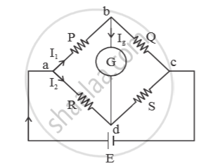
Let `I_3` and `I_4` be the currents in resistors Q and S respectively . Let `I_g` be the current through galvanometer. For balanced condition,
`I_g = 0`
Applying junction law at ‘b’ we get
`I_1 = I_3 + I_g`
`because I_g = 0 , I_1 = I_3` ....(i)
Applying junction law at ‘d’, we get
`I_2 + I_g = I_4`
`because I_g = 0 , I_2 = I_4` ....(ii)
Applying loop law in the loop abda, we get
`-I_1·P - I_g·Q + -I_2·R = 0`
⇒ `-I_1P + I_2R = 0` (`because I_g = 0`)
⇒ `I_1P = I_2R`
⇒ `P/R = I_2/I_1` ....(iii)
Applying loop law in the loop bcdb, we get
`-I_3·Q + I_4·S + I_g·6 = 0`
⇒ `-I_3·Q + I_4·S + 0 = 0 (because I_g =0)`
⇒ `-I_3Q = I_4S`
⇒ `Q/S = I_4/I_3`
⇒ `Q/S = I_2/I_1` ...(iv) [using eq.(i) and (ii)]
From eq. (iii) and (iv), `P/ R = Q/s`
⇒ `P/Q = R/S`
This is the balanced condition.
V ∝ L ⇒ V = xL
Statement
When a Wheatstone bridge is balanced, that is, when there is no deflection in the galvanometer, the ratio of the resistances of any two adjacent arms is equal to the ratio of the resistances of the remaining two adjacent arms, i.e.,
\[\frac {P}{Q}\] = \[\frac {R}{S}\]
Explanation/Proof
In a Wheatstone bridge, four resistances P, Q, R, and S are connected to form the four arms of a parallelogram. A galvanometer is connected across one diagonal and a cell across the other diagonal.
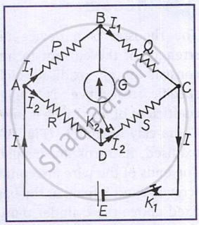
When the key is pressed, the current entering the junction is divided into two parts: current I1 flows through arm AB, and current I2 flows through arm AD. The resistances are adjusted such that there is no current through the galvanometer, indicating that the bridge is balanced.
Since there is no current in the diagonal BD, the same current I1 flows through arms AB and BC, and the same current I2 flows through arms AD and DC.
Applying Kirchhoff’s second law to loop ABDA,
I1P − I2R = 0 ⇒ I1P = I2R ---(i)
Applying Kirchhoff’s second law to loop BCDB,
I1Q − I2S = 0 ⇒ I1Q = I2S ---(ii)
Dividing equation (i) by equation (ii),
Statement
In an electric circuit, the 'algebraic' sum of the currents meeting at any junction in the circuit is zero, that is, ∑ I = 0.
Proof
When applying this law, currents entering the junction are taken as positive, while currents leaving the junction are taken as negative.
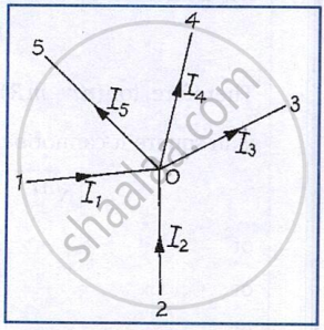
Consider a junction O where five conductors meet, carrying currents I1, I2, I3, I4 and I5.
Let I1 and I2 enter the junction, and I3, I4 and I5 leave the junction.
According to Kirchhoff’s first law,
∑ I = 0
That is,
I1 + I2 − I3 − I4 − I5 = 0
or,
I1 + I2 = I3 + I4 + I5
Thus, the sum of incoming currents is equal to the sum of outgoing currents.
Conclusion
Kirchhoff’s first law, also called Kirchhoff’s current law (KCL), states that when a steady current flows in a circuit, no charge accumulates at any junction. Hence, the law is a direct consequence of the principle of conservation of electric charge.
Statement
In any closed loop of a circuit, the algebraic sum of the products of current and the resistance in each part of the loop is equal to the algebraic sum of the emfs in that loop, that is,
∑ IR = ∑ E
Proof
While applying Kirchhoff’s second law, the following sign conventions are used:
- When we traverse a resistance in the direction of current, the product I R is taken as positive.
- The emf is taken as positive when we traverse from the negative to the positive electrode of the cell through the electrolyte.
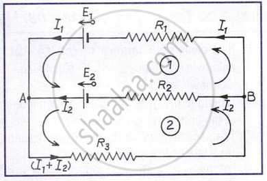
Consider the circuit shown, containing two cells of emfs E1 and E2 and three resistances R1, R2, and R3. Let the currents in R1 and R2 be I1 and I2, respectively. Applying Kirchhoff’s first law at junction A, the current through R3 is I1 + I2.
The circuit has two closed loops.
For loop 1, applying Kirchhoff’s second law:
I1R1 − I2R2 = E1 − E2
For loop 2, applying Kirchhoff’s second law:
I2R2 + (I1 + I2)R3 = E2
Key Points
- Battery and the need for a combination of cells
A single cell cannot give a strong current, so two or more cells are combined to form a battery to obtain a suitable current or emf. - A series combination of cells
In a series combination, emfs and internal resistances add up. It is useful when the external resistance is much larger than the internal resistance. - Parallel combination of cells
In parallel combination, the emf remains the same as one cell, but the internal resistance decreases. It is useful when the external resistance is small. - Mixed grouping of cells
In mixed grouping, cells are connected in series and parallel to obtain both a large current and a suitable emf.
Imax = \[\frac {nE}{2R}\] - Condition for maximum current in mixed grouping
Maximum current flows when the battery's internal resistance equals the external resistance. i.e. \[\frac {nr}{m}\] = R
- Purpose of a rheostat: A rheostat is used to control the current in an electric circuit by changing resistance.
- Construction: It has a Nichrome wire wound on a china-clay cylinder with a sliding contact.
- As a current controller: When connected through A–C or B–C, moving the sliding contact changes the current in the circuit.
- As a potential divider: When connected across A and B, and the circuit is taken from A–C (or B–C), the rheostat provides a variable fraction of the applied potential difference.
- Working principle: Sliding the contact changes the wire's effective length, thereby changing its resistance.
- Principle: The metre bridge works on the Wheatstone bridge principle, and balance is obtained at the null point where the galvanometer shows no deflection.
- Null point condition: At the null point, points B and D are at the same potential and
\[\frac {P}{Q}\] = \[\frac {R}{S}\] - Finding unknown resistance: If the wire is divided into lengths l and 100 − l, the unknown resistance is
S = R\[\frac {(100−l)}{l}\]. - Reducing errors: Errors are reduced by interchanging the known and unknown resistances and taking the mean value.
- Precautions: Keep the null point near the middle, avoid heating the wire, and press the jockey lightly without rubbing.
- Null-deflection method: At balance, no current flows through the galvanometer, making the measurement independent of the cell's internal resistance.
- Uniform wire requirement: The potentiometer wire must have a uniform cross-section and material so that the potential drop along the wire is uniform.
- True emf measurement: The emf is measured in open circuit, ensuring the true value of the emf is obtained without energy loss in the cell.
- Sensitivity dependence: The sensitivity of a potentiometer increases as the potential gradient decreases, using a long wire and low current.
- Experimental precautions: Current should not flow for a long time to avoid heating of the wire, and touch the jockey lightly to prevent wire damage.
Important Questions [17]
- Ε1 and ε2 Are Two Batteries Having Emf of 34v and 10v Respectively and Internal Resistance of 1ω and 2ω Respectively. They Are Connected as Shown in the Figure Below. Using Kirchhoff’S Laws of Electrical Networks, Calculate the Currents I1 and I2
- In the circuit shown in Figure below, E1 and E2 are batteries having emfs of 25V and 26V. They have an internal resistance of 1 Ω and 5 Ω respectively.
- Figure 2 below shows two batteries E1 and E2 having emfs of 18V and 10V and internal resistances of 1 Ω and 2 Ω, respectively. W1, W2 and W3 are uniform metallic wires AC, FD and BE having
- On Which Conservation Principle Is Kirchoff'S Second Law of Electrical Networks Based?
- In the Circuit Shown in Figure Below, E1 and E2 Are Two Cells Having Emfs 2 V and 3 V Respectively, and Negligible Internal Resistances.
- Write balancing condition of a Wheatstone bridge.
- With the help of a labelled diagram, show that the balancing condition of a Wheatstone bridge is 𝑅1𝑅2 =𝑅3𝑅4 where the terms have their usual meaning.
- Obtain the Balancing Condition for the Wheatstone Bridge Arrangements as Shown in Figure 4 Below:
- An I0m Long Uniform Metallic Wire Having a Resistance of 20ω is Used as A Potentiometer Wire. this Wire is Connected in Series with Another Resistance of 480ω and a Battery of Emf 5v Having Negligible Internal Resistance. If an Unknown Emf E is Balanced Across 6m of the Potentiometer Wire, Calculate
- A meter bridge is balanced with a known resistance (R) in the left hand gap and an unknown resistance (S) in the right hand gap.
- The Figure below shows a potentiometer circuit in which the driver cell D has an emf of 6 V and internal resistance of 2 Ω. The potentiometer wire AB is 10 m long and has a resistance of 28 Ω.
- In a Potentiometer Experiment, the Balancing Length with a Resistance of 2ω is Found to Be 100 Cm, While that of an Unknown Resistance is 500 Cm. Calculate the Value of the Unknown Resistance.
- Draw a Labelled Circuit Diagram of a Potentiometer to Measure the Internal Resistance ‘R’ of a Cell. Write the Working Formula (Derivation is Not Required).
- Figure Below Shows Two Resistors R1 and R2 Connected to a Battery Having an Emf of 40v and Negligible Internal Resistance.
- Draw a Labelled Circuit Diagram of a Potentiometer to Compare Emfs of Two Cells. Write the Working Formula (Derivation Not Required).
- Three identical cells each of emf 'e' are connected in parallel to form a battery. What is the emf of the battery?
- In a Potentiometer Experiment, Balancing Length is Found to Be 120 Cm for a Cell E1 of Emf 2v. What Will Be the Balancing Length for Another Cell E2 of Emf 1.5v? (No Other Changes Are Made in the Experiment.)
