Advertisements
Advertisements
Question
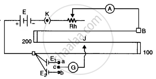
Draw a labelled circuit diagram of a potentiometer to compare emfs of two cells. Write the working formula (Derivation not required).
Advertisements
Solution
The required circuit diagram is given alongside.
Working formula `"E"_1/"E"_2 = l_1/l_2`
APPEARS IN
RELATED QUESTIONS
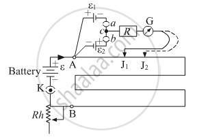
A student uses the circuit diagram of a potentiometer as shown in the figure
(a) for a steady current I passing through the potentiometer wire, he gets a null point for the cell ε1. and not for ε2. Give the reason for this observation and suggest how this difficulty can be resolved.
(b) What is the function of resistance R used in the circuit? How will the change in its value affect the null point?
(c) How can the sensitivity of the potentiometer be increased?
The resistance of a potentiometer wire is 8 Ω and its length is 8 m. A resistance box and a 2 V battery are connected in series with iL What should be the resistance in the box if it is desired to have a potential drop of 1 µV/mm?
The emf of a standard cell is 1.5V and is balanced by a length of 300 cm of a potentiometer with a 10 m long wire. Find the percentage error in a voltmeter that balances at 350 cm when its reading is 1.8 V.
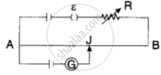
AB is a wire of potentiometer with the increase in the value of resistance R, the shift in the balance point J will be ______.
A wire of resistance R is cut into two equal part. There parts are then connected in parallel. The equivalent resistance of the combination will be
1°C rise in temperature is observed in a conductor by passing a certain current. If the current is double then the rise in temperature is approximately.
As a cell age, its internal resistance increases. A voltmeter of resistance 270 Ω connected across an old dry cell reads 1.44 V. However, a potentiometer at the balance point gives a voltage measurement of the cell as 1.5 V. Internal resistance of the cell is ______ Ω.
If you are provided a set of resistances 2Ω, 4Ω, 6Ω and 8Ω. Connect these resistances so as to obtain an equivalent resistance of `46/3`Ω.
The emf of the cell of internal resistance 1.275 Ω balances against a length of 217 cm of a potentiometer wire. Find the balancing length when the cell is shunted by a resistance of 15 Ω.
Draw a neat labelled diagram of Internal resistance of a cell using a potentiometer.
