Advertisements
Advertisements
Question
When do you say that the resistors are connected in this way? Draw a circuit diagram.
Advertisements
Solution
Resistors connected in series: - If the number of resistance are connected one after another in such a way that the same current flows through each resistance, then the arrangement is called resistance in series.
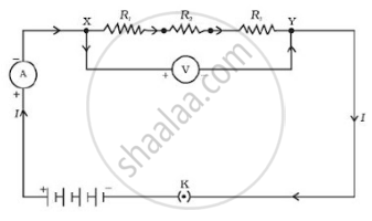
Let R1, R2, and R3 are three resistances connected in a series combination and let be their effective resistance in the circuit.
Let V1, V2, and V3 be the P.D. across resistances R1, R2, and R3 respectively. Let ‘V’ be the P.D. of the cell. Let ‘I’ be the current flow through each resistance.
According to Ohm’s Law,
Conclusion:
If the resistors are connected in series then.
- In a circuit, the current is the same in every part of the circuit.
- The resistance of the combination of resistors is equal to the sum of the individual resistors.
- The total voltage across the combination is equal to the sum of the voltage drop across the separate resistors.
- The effective resistance in a series combination is greater than the individual resistances.
- This combination is used to increase resistance in a circuit.
APPEARS IN
RELATED QUESTIONS
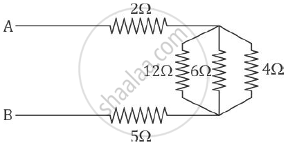
Find the equivalent resistance between points A and B.
When a 4 Ω resistor is connected across the terminals of a 12 V battery, the number of coulombs passing through the resistor per second is:
(a) 0.3
(b) 3
(c) 4
(d) 12
If the length of a wire is doubled by taking more of wire, what happens to its resistance?
How does the resistance of a wire change when:
its diameter is tripled?
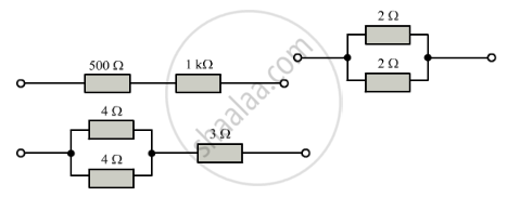
Calculate the combined resistance in each case:
What is (a) highest, and (b)Ω lowest, resistance which can be obtained by combining four resistors having the following resistances?
4 Ω, 8 Ω, 12 Ω, 24 Ω
Choose the correct alternative and rewrite the following sentence.
If three resistors 2 ohms, 3 ohms and 4 ohms are connected in series, then the effective resistance in the circuit will be _______ ohms.
Name the material of wire used for making standard resistances. Give a reason.
How does the resistivity of an alloy such as constantace depends on temperature.
The voltage applied to a given rheostat is made four times its initial value. By what factor will be resistance of the rheostat change?
State a relation between electrical power, resistance and potential difference in an electrical circuit.
You are provided with three resistors of resistance 1.0 Ω, 2.0 Ω and 3.0 Ω How would you connect them to obtain the total effective resistance 1.5 Ω? Draw diagram of the arrangement and check it by calculations.
Illustrate-combination of cells e.g., three cells, in series, explaining the combination briefly. Obtain an expression for current ‘i’ in the combination.
What should be the length of a nickel wire of area of cross-section 3 mm2 used for making a rheostat of 750 ohm? (ρ of nickle = 0.069 Ohm mm2/m)
Two resistors having 2Ω and 3Ω resistance are connected—(i) in series, and (ii) in parallel. Find the equivalent resistance in each case.
In an electrical circuit, two resistors of 2 Ω and 4 Ω respectively are connected in series to a 6 V battery. The heat dissipated by the 4 Ω resistor in 5 s will be ______.
