Advertisements
Advertisements
Question
Suppose a charge +Q1 is given to the positive plate and a charge −Q2 to the negative plate of a capacitor. What is the "charge on the capacitor"?
Advertisements
Solution
Given :
Charge on the positive plane = `+Q_1`
Charge on the negative plate = `-Q_2`
To calculate: Charge on the capacitor
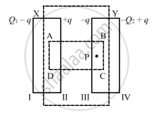
Let ABCD be the Gaussian surface such that faces AD and BC lie inside plates X and Y, respectively.
Let q be the charge appearing on surface II. Then, the distribution of the charges on faces I, III and IV will be in accordance with the figure.
Let the area of the plates be A and the permittivity of the free space be `∈_0`.
Now, to determine q in terms of Q1 and Q2, we need to apply Gauss's law to calculate the electric field due to all four faces of the capacitor at point P. Also, we know that the electric field inside a capacitor is zero.
Electric field due to face I at point P, E1 = `(Q_1 - q)/(2∈_0A)`
Electric field due to face II at point P, E2= `(+q)/(2∈_0A)`
Electric field due to face III at point P, E3 = `(-q)/{2∈_0A)`
Electric field due to face IV at point P, E4 = `-((-Q_2+q)/(2∈_0A))` (Negative sign is used as point P lies on the LHS of face IV.)
Since point P lies inside the conductor,
E1 + E2 + E3 + E4 = 0
`therefore` `Q_1-q+q-q-(-Q_2+q)` = 0
⇒ q = `(Q_1+Q_2)/2`
Thus , the change on the capacitor is `(Q_1+Q_2)/2`, which is the charge on faces II and III.
APPEARS IN
RELATED QUESTIONS
A cylindrical capacitor has two co-axial cylinders of length 15 cm and radii 1.5 cm and 1.4 cm. The outer cylinder is earthed and the inner cylinder is given a charge of 3.5 µC. Determine the capacitance of the system and the potential of the inner cylinder. Neglect end effects (i.e., bending of field lines at the ends).
A circuit is set up by connecting inductance L = 100 mH, resistor R = 100 Ω and a capacitor of reactance 200 Ω in series. An alternating emf of \[150\sqrt{2}\] V, 500/π Hz is applies across this series combination. Calculate the power dissipated in the resistor.
Each plate of a parallel plate capacitor has a charge q on it. The capacitor is now connected to a batter. Now,
(a) the facing surfaces of the capacitor have equal and opposite charges
(b) the two plates of the capacitor have equal and opposite charges
(c) the battery supplies equal and opposite charges to the two plates
(d) the outer surfaces of the plates have equal charges
A parallel-plate capacitor is connected to a battery. A metal sheet of negligible thickness is placed between the plates. The sheet remains parallel to the plates of the capacitor.
A capacitor of capacitance 5⋅00 µF is charged to 24⋅0 V and another capacitor of capacitance 6⋅0 µF is charged to 12⋅0 V. (a) Find the energy stored in each capacitor. (b) The positive plate of the first capacitor is now connected to the negative plate of the second and vice versa. Find the new charges on the capacitors. (c) Find the loss of electrostatic energy during the process. (d) Where does this energy go?
A wire of resistance ‘R’ is cut into ‘n’ equal parts. These parts are then connected in parallel with each other. The equivalent resistance of the combination is:
An ac circuit consists of a series combination of circuit elements X and Y. The current is ahead of the voltage in phase by `pi/4`. If element X is a pure resistor of 100 Ω,
(a) name the circuit element Y.
(b) calculate the rms value of current, if rms of voltage is 141 V.
(c) what will happen if the ac source is replaced by a dc source
Two parallel plate capacitors X and Y, have the same area of plates and same separation between plates. X has air and Y with dielectric of constant 2, between its plates. They are connected in series to a battery of 12 V. The ratio of electrostatic energy stored in X and Y is ______.
Two equal capacitors are first connected in series and then in parallel The ratio of the equivalent capacities in the two cases will be ______.
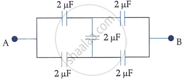
In the following circuit, the equivalent capacitance between terminal A and terminal B is:
What is the work done per unit charge in moving a charge from one plate of a capacitor to the other called?
What is the charge relationship for capacitors in series?
How is the total voltage related to the voltages across capacitors in series?
For two capacitors in series, which expression gives the voltage across the first capacitor?
For two capacitors in series, which expression gives the voltage across the second capacitor?
In a series combination, which capacitor has the larger voltage drop?
Compared with the individual capacitors in a parallel combination, how large is the equivalent capacitance?
Which expressions give the energy stored in series and parallel combinations, respectively?
A charge of \[1.6\times10^{-11}\,\mathrm{C}\] produces a potential difference of \[10\,\mathrm{V}\]. What capacitance follows from \[C=\frac{Q}{V}\]?
