Advertisements
Advertisements
Question
A circuit is set up by connecting inductance L = 100 mH, resistor R = 100 Ω and a capacitor of reactance 200 Ω in series. An alternating emf of \[150\sqrt{2}\] V, 500/π Hz is applies across this series combination. Calculate the power dissipated in the resistor.
Advertisements
Solution
Given the r.m.s value of emf in the circuit Ev = 150√2 V
The impedance of the LCR- circuit is given by
\[Z = \sqrt{R^2 + \left( X_L - X_C \right)^2}\]
\[ = \sqrt{R^2 + \left( 2\pi fL - 200 \right)^2}\]
\[ = \sqrt{{100}^2 + \left( 2\pi \times \frac{500}{\pi} \times 0 . 1 - 200 \right)^2}\]
\[ = 100\sqrt{2} \Omega\]
The r.m.s value of current Iv in the circuit is given by
\[I_v = \frac{E_v}{Z} = \frac{150\sqrt{2}}{100\sqrt{2}} = 1 . 5 A\]
Power dissipated in the resistor = EvIv = 318.2 W
APPEARS IN
RELATED QUESTIONS
Two capacitors of unknown capacitances C1 and C2 are connected first in series and then in parallel across a battery of 100 V. If the energy stored in the two combinations is 0.045 J and 0.25 J respectively, determine the value of C1 and C2. Also calculate the charge on each capacitor in parallel combination.
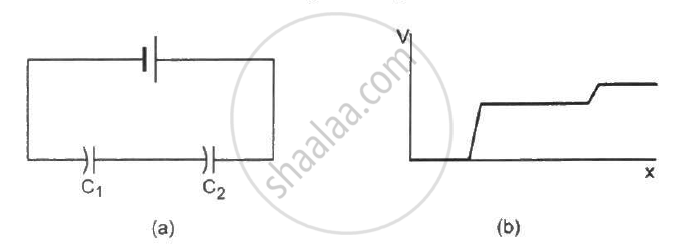
The following figure shows two capacitors connected in series and joined to a battery. The graph shows the variation in potential as one moves from left to right on the branch containing the capacitors.
A parallel-plate capacitor having plate area 20 cm2 and separation between the plates 1⋅00 mm is connected to a battery of 12⋅0 V. The plates are pulled apart to increase the separation to 2⋅0 mm. (a) Calculate the charge flown through the circuit during the process. (b) How much energy is absorbed by the battery during the process? (c) Calculate the stored energy in the electric field before and after the process. (d) Using the expression for the force between the plates, find the work done by the person pulling the plates apart. (e) Show and justify that no heat is produced during this transfer of charge as the separation is increased.
Capacitors connected in series have ______
In the circuit shown in figure, initially K1 is closed and K2 is open. What are the charges on each capacitors.
Then K1 was opened and K2 was closed (order is important), What will be the charge on each capacitor now? [C = 1µF]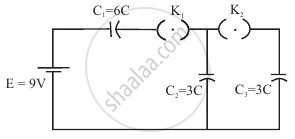
The total charge on the system of capacitors C1 = 1 µF, C2 = 2 µF, C3 = 4 µF and C4 = 3 µF connected in parallel is ______. (Assume a battery of 20 V is connected to the combination)
The potential difference that must be applied across the series and parallel combination of 4 identical capacitors such that the energy stored in them becomes the same. The ratio of potential difference in series to parallel combination is ______.
For two capacitors in series, which expression gives the voltage across the first capacitor?
For two capacitors in series, which expression gives the voltage across the second capacitor?
How is the total charge related to the charges on capacitors in parallel?
