Advertisements
Advertisements
Question
An electrical technician requires a capacitance of 2 µF in a circuit across a potential difference of 1 kV. A large number of 1 µF capacitors are available to him each of which can withstand a potential difference of not more than 400 V. Suggest a possible arrangement that requires the minimum number of capacitors.
Advertisements
Solution
Total required capacitance, C = 2 µF
Potential difference, V = 1 kV = 1000 V
Capacitance of each capacitor, C1 = 1µF
Each capacitor can withstand a potential difference, V1 = 400 V
Suppose a number of capacitors are connected in series and these series circuits are connected in parallel (row) to each other. The potential difference across each row must be 1000 V and the potential difference across each capacitor must be 400 V. Hence, the number of capacitors in each row is given as
`1000/400 = 2.5`
Hence, there are three capacitors in each row.
Capacitance of each row
= `1/(1 + 1 + 1)`
= `1/3 mu "F"`
Let there are n rows, each having three capacitors, which are connected in parallel. Hence, equivalent capacitance of the circuit is given as
`1/3 + 1/3 + 1/3 +.................. "n terms"`
= `"n"/3`
However, the capacitance of the circuit is given as 2 `mu"F"`
∴ `"n"/3 = 2`
n = 6
Hence, 6 rows of three capacitors are present in the circuit. A minimum of 6 × 3 i.e., 18 capacitors are required for the given arrangement.
APPEARS IN
RELATED QUESTIONS
Two capacitors of unknown capacitances C1 and C2 are connected first in series and then in parallel across a battery of 100 V. If the energy stored in the two combinations is 0.045 J and 0.25 J respectively, determine the value of C1 and C2. Also calculate the charge on each capacitor in parallel combination.
Three capacitors each of capacitance 9 pF are connected in series.
- What is the total capacitance of the combination?
- What is the potential difference across each capacitor if the combination is connected to a 120 V supply?
Figure 4 below shows a capacitor C, an inductor L and a resistor R, connected in series
to an a.c. supply of 220 V
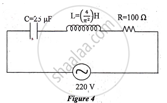
Calculate:
1) The resonant frequency of the given CLR circuit.
2) Current flowing through·the circuit.
3) Average power consumed by the circuit.
A circuit is set up by connecting inductance L = 100 mH, resistor R = 100 Ω and a capacitor of reactance 200 Ω in series. An alternating emf of \[150\sqrt{2}\] V, 500/π Hz is applies across this series combination. Calculate the power dissipated in the resistor.
Suppose a charge +Q1 is given to the positive plate and a charge −Q2 to the negative plate of a capacitor. What is the "charge on the capacitor"?
A parallel-plate capacitor has plates of unequal area. The larger plate is connected to the positive terminal of the battery and the smaller plate to its negative terminal. Let Q, and Q be the charges appearing on the positive and negative plates respectively.
Each plate of a parallel plate capacitor has a charge q on it. The capacitor is now connected to a batter. Now,
(a) the facing surfaces of the capacitor have equal and opposite charges
(b) the two plates of the capacitor have equal and opposite charges
(c) the battery supplies equal and opposite charges to the two plates
(d) the outer surfaces of the plates have equal charges
The plates of a capacitor are 2⋅00 cm apart. An electron-proton pair is released somewhere in the gap between the plates and it is found that the proton reaches the negative plate at the same time as the electron reaches the positive plate. At what distance from the negative plate was the pair released?
Three capacitors of capacitance `C_1 = 3muf` , `C_2 = 6muf` , `C_3 = 10muf` , are connected to a 10V battery as shown in figure 3 below :
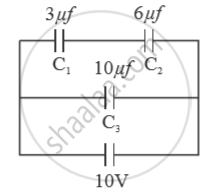
Calculate :
(a) Equivalent capacitance.
(b) Electrostatic potential energy stored in the system
An ac circuit consists of a series combination of circuit elements X and Y. The current is ahead of the voltage in phase by `pi/4`. If element X is a pure resistor of 100 Ω,
(a) name the circuit element Y.
(b) calculate the rms value of current, if rms of voltage is 141 V.
(c) what will happen if the ac source is replaced by a dc source
Three capacitors each of 4 µF are to be connected in such a way that the effective capacitance is 6µF. This can be done by connecting them:
Three different capacitors are·connected in series. Then:-
In the circuit shown in figure, initially K1 is closed and K2 is open. What are the charges on each capacitors.
Then K1 was opened and K2 was closed (order is important), What will be the charge on each capacitor now? [C = 1µF]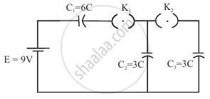
Two charges q1 and q2 are placed at (0, 0, d) and (0, 0, – d) respectively. Find locus of points where the potential a zero.
Two equal capacitors are first connected in series and then in parallel The ratio of the equivalent capacities in the two cases will be ______.
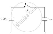
A capacitor of capacity C1 is charged to the potential of V0. On disconnecting with the battery, it is connected with an uncharged capacitor of capacity C2 as shown in the adjoining figure. Find the ratio of energies before and after the connection of switch S.
The potential difference that must be applied across the series and parallel combination of 4 identical capacitors such that the energy stored in them becomes the same. The ratio of potential difference in series to parallel combination is ______.
