Advertisements
Advertisements
प्रश्न
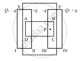
Suppose a charge +Q1 is given to the positive plate and a charge −Q2 to the negative plate of a capacitor. What is the "charge on the capacitor"?
Advertisements
उत्तर
Given :
Charge on the positive plane = `+Q_1`
Charge on the negative plate = `-Q_2`
To calculate: Charge on the capacitor
Let ABCD be the Gaussian surface such that faces AD and BC lie inside plates X and Y, respectively.
Let q be the charge appearing on surface II. Then, the distribution of the charges on faces I, III and IV will be in accordance with the figure.
Let the area of the plates be A and the permittivity of the free space be `∈_0`.
Now, to determine q in terms of Q1 and Q2, we need to apply Gauss's law to calculate the electric field due to all four faces of the capacitor at point P. Also, we know that the electric field inside a capacitor is zero.
Electric field due to face I at point P, E1 = `(Q_1 - q)/(2∈_0A)`
Electric field due to face II at point P, E2= `(+q)/(2∈_0A)`
Electric field due to face III at point P, E3 = `(-q)/{2∈_0A)`
Electric field due to face IV at point P, E4 = `-((-Q_2+q)/(2∈_0A))` (Negative sign is used as point P lies on the LHS of face IV.)
Since point P lies inside the conductor,
E1 + E2 + E3 + E4 = 0
`therefore` `Q_1-q+q-q-(-Q_2+q)` = 0
⇒ q = `(Q_1+Q_2)/2`
Thus , the change on the capacitor is `(Q_1+Q_2)/2`, which is the charge on faces II and III.
APPEARS IN
संबंधित प्रश्न
Two capacitors of unknown capacitances C1 and C2 are connected first in series and then in parallel across a battery of 100 V. If the energy stored in the two combinations is 0.045 J and 0.25 J respectively, determine the value of C1 and C2. Also calculate the charge on each capacitor in parallel combination.
Three capacitors of capacitances 2 pF, 3 pF and 4 pF are connected in parallel. Determine the charge on each capacitor if the combination is connected to a 100 V supply.
An electrical technician requires a capacitance of 2 µF in a circuit across a potential difference of 1 kV. A large number of 1 µF capacitors are available to him each of which can withstand a potential difference of not more than 400 V. Suggest a possible arrangement that requires the minimum number of capacitors.
Deduce an expression for equivalent capacitance C when three capacitors C1, C2 and C3 connected in parallel.
Figure 4 below shows a capacitor C, an inductor L and a resistor R, connected in series
to an a.c. supply of 220 V
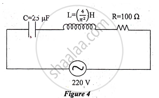
Calculate:
1) The resonant frequency of the given CLR circuit.
2) Current flowing through·the circuit.
3) Average power consumed by the circuit.
If the capacitors in the previous question are joined in parallel, the capacitance and the breakdown voltage of the combination will be
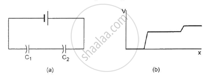
The following figure shows two capacitors connected in series and joined to a battery. The graph shows the variation in potential as one moves from left to right on the branch containing the capacitors.
Each plate of a parallel plate capacitor has a charge q on it. The capacitor is now connected to a batter. Now,
(a) the facing surfaces of the capacitor have equal and opposite charges
(b) the two plates of the capacitor have equal and opposite charges
(c) the battery supplies equal and opposite charges to the two plates
(d) the outer surfaces of the plates have equal charges
A parallel-plate capacitor is connected to a battery. A metal sheet of negligible thickness is placed between the plates. The sheet remains parallel to the plates of the capacitor.
A capacitor of capacitance 5⋅00 µF is charged to 24⋅0 V and another capacitor of capacitance 6⋅0 µF is charged to 12⋅0 V. (a) Find the energy stored in each capacitor. (b) The positive plate of the first capacitor is now connected to the negative plate of the second and vice versa. Find the new charges on the capacitors. (c) Find the loss of electrostatic energy during the process. (d) Where does this energy go?
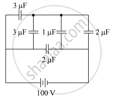
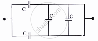
The figure shows a network of five capacitors connected to a 100 V supply. Calculate the total energy stored in the network.
An ac circuit consists of a series combination of circuit elements X and Y. The current is ahead of the voltage in phase by `pi/4`. If element X is a pure resistor of 100 Ω,
(a) name the circuit element Y.
(b) calculate the rms value of current, if rms of voltage is 141 V.
(c) what will happen if the ac source is replaced by a dc source
Three different capacitors are·connected in series. Then:-
Two charges q1 and q2 are placed at (0, 0, d) and (0, 0, – d) respectively. Find locus of points where the potential a zero.
The equivalent capacitance of the combination shown is: