Advertisements
Advertisements
प्रश्न
Figure 4 below shows a capacitor C, an inductor L and a resistor R, connected in series
to an a.c. supply of 220 V
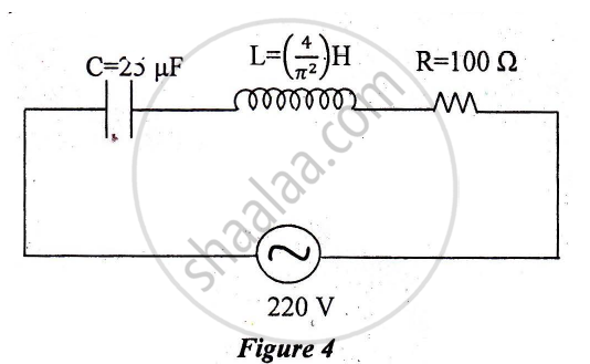
Calculate:
1) The resonant frequency of the given CLR circuit.
2) Current flowing through·the circuit.
3) Average power consumed by the circuit.
Advertisements
उत्तर
`E_"rms" = 220 V`
`C = 25 muF`
`L = (4/pi^2)H`
R = 100 Ω
1) Resonant Frequency
`f_r = 1/(2pisqrt(LC))`
`= 1/(2xx 3.14 xx sqrt(4/pi^2 xx 25 xx 10^(-6)))`
`= 1/(2xx3.14 xx 2/3.14 xx 5 xx 10^(-3)) `
= 50 Hz
2) Inpedance (Z) = `sqrt(R^2 + (X_L - X_C)^2)`
`X_L = 127.3 Ω, X_C = 127.3 Ω`
Z = `sqrt(100^2 + (127.3 - 127.3)^2 )`
`Z = sqrt(100^2)`
Z = 100 Ω
`I_"rms" = E_"rms"/2`
`= 220/100`
`I_"rms" = 2.2 A`
3) Average power consumed by the circuit
Power = `E_"rms" xx I_"rms" xx R/sqrt(R^2 + (Lomega - 1/(Comega)))`
z = R
∴ Power = `E_"rms" xx I_"rms"`
Power = 484 watt
APPEARS IN
संबंधित प्रश्न
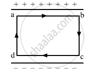
The electric field inside a parallel plate capacitor is E. Find the amount of work done in moving a charge q over a closed loop a b c d a.
A cylindrical capacitor has two co-axial cylinders of length 15 cm and radii 1.5 cm and 1.4 cm. The outer cylinder is earthed and the inner cylinder is given a charge of 3.5 µC. Determine the capacitance of the system and the potential of the inner cylinder. Neglect end effects (i.e., bending of field lines at the ends).
If the capacitors in the previous question are joined in parallel, the capacitance and the breakdown voltage of the combination will be
Each plate of a parallel plate capacitor has a charge q on it. The capacitor is now connected to a batter. Now,
(a) the facing surfaces of the capacitor have equal and opposite charges
(b) the two plates of the capacitor have equal and opposite charges
(c) the battery supplies equal and opposite charges to the two plates
(d) the outer surfaces of the plates have equal charges
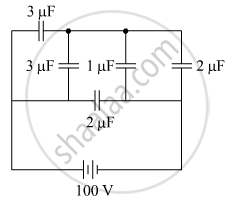
The figure shows a network of five capacitors connected to a 100 V supply. Calculate the total energy stored in the network.
An ac circuit consists of a series combination of circuit elements X and Y. The current is ahead of the voltage in phase by `pi/4`. If element X is a pure resistor of 100 Ω,
(a) name the circuit element Y.
(b) calculate the rms value of current, if rms of voltage is 141 V.
(c) what will happen if the ac source is replaced by a dc source
Three different capacitors are·connected in series. Then:-
The potential difference that must be applied across the series and parallel combination of 4 identical capacitors such that the energy stored in them becomes the same. The ratio of potential difference in series to parallel combination is ______.
What is the charge relationship for capacitors in series?
Compared with the individual capacitors in a series combination, how large is the equivalent capacitance?
