Advertisements
Advertisements
प्रश्न
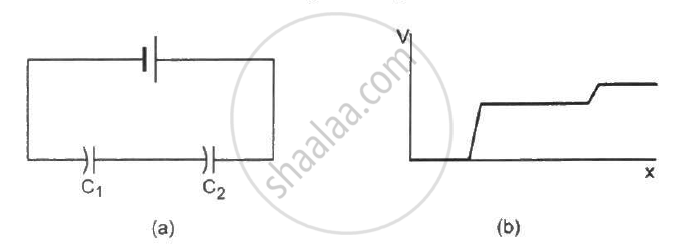
The following figure shows two capacitors connected in series and joined to a battery. The graph shows the variation in potential as one moves from left to right on the branch containing the capacitors.
विकल्प
C1 > C2
C1 = C2
C1 < C2
The information is not sufficient to decide the relation between C1 and C2.
Advertisements
उत्तर
C1 < C2
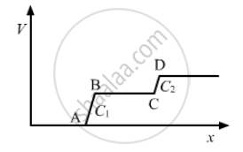
Region AB shows the potential difference across capacitor C1 and region CD shows the potential difference across capacitor C2. Now, we can see from the graph that region AB is greater than region CD. Therefore, the potential difference across capacitor C1 is greater than that across capacitor C2.
∵ Capacitance, C = `Q/V`
∴ C1 < C2 (Q remains the same in series connection.)
APPEARS IN
संबंधित प्रश्न
Three capacitors of capacitances 2 pF, 3 pF and 4 pF are connected in parallel. Determine the charge on each capacitor if the combination is connected to a 100 V supply.
Suppose a charge +Q1 is given to the positive plate and a charge −Q2 to the negative plate of a capacitor. What is the "charge on the capacitor"?
The plates of a parallel-plate capacitor are given equal positive charges. What will be the potential difference between the plates? What will be the charges on the facing surfaces and on the outer surfaces?
If the capacitors in the previous question are joined in parallel, the capacitance and the breakdown voltage of the combination will be
A parallel-plate capacitor has plates of unequal area. The larger plate is connected to the positive terminal of the battery and the smaller plate to its negative terminal. Let Q, and Q be the charges appearing on the positive and negative plates respectively.
A parallel-plate capacitor having plate area 20 cm2 and separation between the plates 1⋅00 mm is connected to a battery of 12⋅0 V. The plates are pulled apart to increase the separation to 2⋅0 mm. (a) Calculate the charge flown through the circuit during the process. (b) How much energy is absorbed by the battery during the process? (c) Calculate the stored energy in the electric field before and after the process. (d) Using the expression for the force between the plates, find the work done by the person pulling the plates apart. (e) Show and justify that no heat is produced during this transfer of charge as the separation is increased.
A capacitor of capacitance 5⋅00 µF is charged to 24⋅0 V and another capacitor of capacitance 6⋅0 µF is charged to 12⋅0 V. (a) Find the energy stored in each capacitor. (b) The positive plate of the first capacitor is now connected to the negative plate of the second and vice versa. Find the new charges on the capacitors. (c) Find the loss of electrostatic energy during the process. (d) Where does this energy go?
An ac circuit consists of a series combination of circuit elements X and Y. The current is ahead of the voltage in phase by `pi /4` . If element X is a pure resistor of 100Ω ,
(a) name the circuit element Y.
(b) calculate the rms value of current, if rms value of voltage is 141V.
(c) what will happen if the ac source is replaced by a dc source ?
Three different capacitors are·connected in series. Then:-
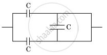
The equivalent capacitance of the combination shown in the figure is ______.
In the circuit shown in figure, initially K1 is closed and K2 is open. What are the charges on each capacitors.
Then K1 was opened and K2 was closed (order is important), What will be the charge on each capacitor now? [C = 1µF]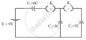
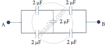
In the following circuit, the equivalent capacitance between terminal A and terminal B is:
What is the work done per unit charge in moving a charge from one plate of a capacitor to the other called?
In a series combination, which capacitor has the larger voltage drop?
How is the total charge related to the charges on capacitors in parallel?
What is the equivalent capacitance of \[n\] identical capacitors, each with capacitance \[C\], connected in parallel?
Which relation gives the charge on one capacitor in a parallel combination when the common voltage is \[V\]?
