Advertisements
Advertisements
प्रश्न
Figure 4 below shows a capacitor C, an inductor L and a resistor R, connected in series
to an a.c. supply of 220 V
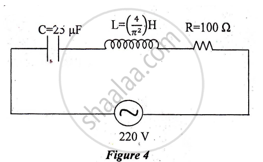
Calculate:
1) The resonant frequency of the given CLR circuit.
2) Current flowing through·the circuit.
3) Average power consumed by the circuit.
Advertisements
उत्तर
`E_"rms" = 220 V`
`C = 25 muF`
`L = (4/pi^2)H`
R = 100 Ω
1) Resonant Frequency
`f_r = 1/(2pisqrt(LC))`
`= 1/(2xx 3.14 xx sqrt(4/pi^2 xx 25 xx 10^(-6)))`
`= 1/(2xx3.14 xx 2/3.14 xx 5 xx 10^(-3)) `
= 50 Hz
2) Inpedance (Z) = `sqrt(R^2 + (X_L - X_C)^2)`
`X_L = 127.3 Ω, X_C = 127.3 Ω`
Z = `sqrt(100^2 + (127.3 - 127.3)^2 )`
`Z = sqrt(100^2)`
Z = 100 Ω
`I_"rms" = E_"rms"/2`
`= 220/100`
`I_"rms" = 2.2 A`
3) Average power consumed by the circuit
Power = `E_"rms" xx I_"rms" xx R/sqrt(R^2 + (Lomega - 1/(Comega)))`
z = R
∴ Power = `E_"rms" xx I_"rms"`
Power = 484 watt
APPEARS IN
संबंधित प्रश्न
Deduce an expression for equivalent capacitance C when three capacitors C1, C2 and C3 connected in parallel.
If the capacitors in the previous question are joined in parallel, the capacitance and the breakdown voltage of the combination will be
Each plate of a parallel plate capacitor has a charge q on it. The capacitor is now connected to a batter. Now,
(a) the facing surfaces of the capacitor have equal and opposite charges
(b) the two plates of the capacitor have equal and opposite charges
(c) the battery supplies equal and opposite charges to the two plates
(d) the outer surfaces of the plates have equal charges
A parallel-plate capacitor is connected to a battery. A metal sheet of negligible thickness is placed between the plates. The sheet remains parallel to the plates of the capacitor.
Three capacitors of capacitance `C_1 = 3muf` , `C_2 = 6muf` , `C_3 = 10muf` , are connected to a 10V battery as shown in figure 3 below :
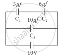
Calculate :
(a) Equivalent capacitance.
(b) Electrostatic potential energy stored in the system
A wire of resistance ‘R’ is cut into ‘n’ equal parts. These parts are then connected in parallel with each other. The equivalent resistance of the combination is:
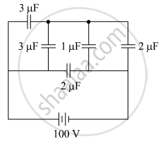
The figure shows a network of five capacitors connected to a 100 V supply. Calculate the total energy stored in the network.
Capacitors connected in series have ______
Two equal capacitors are first connected in series and then in parallel The ratio of the equivalent capacities in the two cases will be ______.
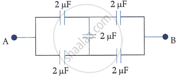
In the following circuit, the equivalent capacitance between terminal A and terminal B is: