Advertisements
Advertisements
प्रश्न
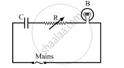
A capacitor 'C', a variable resistor 'R' and a bulb 'B' are connected in series to the ac mains in circuit as shown. The bulb glows with some brightness. How will the glow of the bulb change if (i) a dielectric slab is introduced between the plates of the capacitor, keeping resistance R to be the same; (ii) the resistance R is increased keeping the same capacitance?
Advertisements
उत्तर
(i)As the dielectric slab is introduced between the plates of the capacitor, its capacitance will increase. Hence, the potential drop across the capacitor will decrease (V=`Q/C`). As a result, the potential drop across the bulb will increase (since both are connected in series). So, its brightness will increase.
(ii)As the resistance (R) is increased, the potential drop across the resistor will increase. As a result, the potential drop across the bulb will decrease (since both are connected in series).
So, its brightness will decrease.
APPEARS IN
संबंधित प्रश्न
A circuit is set up by connecting inductance L = 100 mH, resistor R = 100 Ω and a capacitor of reactance 200 Ω in series. An alternating emf of \[150\sqrt{2}\] V, 500/π Hz is applies across this series combination. Calculate the power dissipated in the resistor.
The plates of a capacitor are 2⋅00 cm apart. An electron-proton pair is released somewhere in the gap between the plates and it is found that the proton reaches the negative plate at the same time as the electron reaches the positive plate. At what distance from the negative plate was the pair released?
A wire of resistance ‘R’ is cut into ‘n’ equal parts. These parts are then connected in parallel with each other. The equivalent resistance of the combination is:
An ac circuit consists of a series combination of circuit elements X and Y. The current is ahead of the voltage in phase by `pi/4`. If element X is a pure resistor of 100 Ω,
(a) name the circuit element Y.
(b) calculate the rms value of current, if rms of voltage is 141 V.
(c) what will happen if the ac source is replaced by a dc source
Two parallel plate capacitors X and Y, have the same area of plates and same separation between plates. X has air and Y with dielectric of constant 2, between its plates. They are connected in series to a battery of 12 V. The ratio of electrostatic energy stored in X and Y is ______.
Three capacitors each of 4 µF are to be connected in such a way that the effective capacitance is 6µF. This can be done by connecting them:
In the circuit shown in figure, initially K1 is closed and K2 is open. What are the charges on each capacitors.
Then K1 was opened and K2 was closed (order is important), What will be the charge on each capacitor now? [C = 1µF]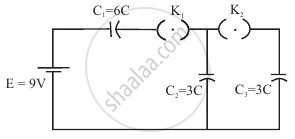
The total charge on the system of capacitors C1 = 1 µF, C2 = 2 µF, C3 = 4 µF and C4 = 3 µF connected in parallel is ______. (Assume a battery of 20 V is connected to the combination)
What is the process of replacing a group of capacitors with a single equivalent capacitor that produces the same electrical effect called?
How is the total voltage related to the voltages across capacitors in series?
