Advertisements
Advertisements
प्रश्न
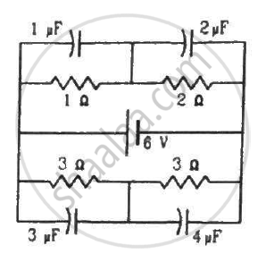
Find the charges on the four capacitors of capacitances 1 μF, 2 μF, 3 μF and 4 μF shown in the figure.
Advertisements
उत्तर
When the capacitors are fully charged, they attain steady state and no current flows through them. Then, equivalent resistance of the circuit,
\[R_{eff} = \frac{3 \times 6}{3 + 6} = 2 \Omega\]
Current through the circuit,
\[i = \frac{6}{2} = 3 A\]
Current i is divided in the inverse ratio of the resistance in each branch. One branch has resistance of 3 Ω and the other branch has resistance of 6 Ω.
Current i' through the 3 Ω branch,
\[i' = \frac{6}{9}i = \frac{2}{3} \times 3 A = 2 A\]
Current i'' through the 6 Ω branch,
\[i'' = i - i' = 1 A\]
Voltage across the 1 Ω resistor = 2 A × 1 Ω = 2 V
Charge on the 1 μF capacitor = 2 × 1 μF = 2 μC
Voltage across the 2 Ω resistor = 2 Ω × 2 A = 4 V
Charge on the 2 μF capacitor = 4V × 2 μF = 8 μC
Voltage across each 3 Ω resistor = 3 Ω × 1 A = 3 V
Charge on the 4 μF capacitor = 3 × 4 μC = 12 μC
Charge on the 3 μF capacitor = 3 × 3 μC = 9 μC
APPEARS IN
संबंधित प्रश्न
The electric field inside a parallel plate capacitor is E. Find the amount of work done in moving a charge q over a closed loop a b c d a.
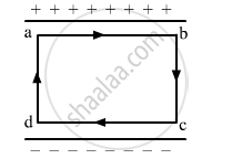
Figure 4 below shows a capacitor C, an inductor L and a resistor R, connected in series
to an a.c. supply of 220 V
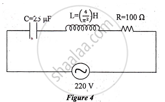
Calculate:
1) The resonant frequency of the given CLR circuit.
2) Current flowing through·the circuit.
3) Average power consumed by the circuit.
If the capacitors in the previous question are joined in parallel, the capacitance and the breakdown voltage of the combination will be
A parallel-plate capacitor has plates of unequal area. The larger plate is connected to the positive terminal of the battery and the smaller plate to its negative terminal. Let Q, and Q be the charges appearing on the positive and negative plates respectively.
A parallel-plate capacitor is connected to a battery. A metal sheet of negligible thickness is placed between the plates. The sheet remains parallel to the plates of the capacitor.
A parallel-plate capacitor having plate area 25 cm2 and separation 1⋅00 mm is connected to a battery of 6⋅0 V. Calculate the charge flown through the battery. How much work has been done by the battery during the process?
The plates of a capacitor are 2⋅00 cm apart. An electron-proton pair is released somewhere in the gap between the plates and it is found that the proton reaches the negative plate at the same time as the electron reaches the positive plate. At what distance from the negative plate was the pair released?
A capacitor of capacitance 5⋅00 µF is charged to 24⋅0 V and another capacitor of capacitance 6⋅0 µF is charged to 12⋅0 V. (a) Find the energy stored in each capacitor. (b) The positive plate of the first capacitor is now connected to the negative plate of the second and vice versa. Find the new charges on the capacitors. (c) Find the loss of electrostatic energy during the process. (d) Where does this energy go?
Three capacitors of capacitance `C_1 = 3muf` , `C_2 = 6muf` , `C_3 = 10muf` , are connected to a 10V battery as shown in figure 3 below :
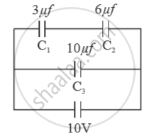
Calculate :
(a) Equivalent capacitance.
(b) Electrostatic potential energy stored in the system
A wire of resistance ‘R’ is cut into ‘n’ equal parts. These parts are then connected in parallel with each other. The equivalent resistance of the combination is:
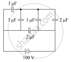
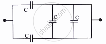
The figure shows a network of five capacitors connected to a 100 V supply. Calculate the total energy stored in the network.
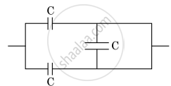
The equivalent capacitance of the combination shown in the figure is ______.
Two charges q1 and q2 are placed at (0, 0, d) and (0, 0, – d) respectively. Find locus of points where the potential a zero.
Two equal capacitors are first connected in series and then in parallel The ratio of the equivalent capacities in the two cases will be ______.
The total charge on the system of capacitors C1 = 1 µF, C2 = 2 µF, C3 = 4 µF and C4 = 3 µF connected in parallel is ______. (Assume a battery of 20 V is connected to the combination)
The equivalent capacitance of the combination shown is: