Advertisements
Advertisements
प्रश्न
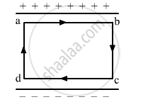
The electric field inside a parallel plate capacitor is E. Find the amount of work done in moving a charge q over a closed loop a b c d a.
Advertisements
उत्तर
Work done, W= F.d
Here, F is the force exerted on the charge (q) due to electric field (E) and is given by:
F=qE
Net displacement, d = 0
∴ W=0
APPEARS IN
संबंधित प्रश्न
A cylindrical capacitor has two co-axial cylinders of length 15 cm and radii 1.5 cm and 1.4 cm. The outer cylinder is earthed and the inner cylinder is given a charge of 3.5 µC. Determine the capacitance of the system and the potential of the inner cylinder. Neglect end effects (i.e., bending of field lines at the ends).
Deduce an expression for equivalent capacitance C when three capacitors C1, C2 and C3 connected in parallel.
Suppose a charge +Q1 is given to the positive plate and a charge −Q2 to the negative plate of a capacitor. What is the "charge on the capacitor"?
The plates of a parallel-plate capacitor are given equal positive charges. What will be the potential difference between the plates? What will be the charges on the facing surfaces and on the outer surfaces?
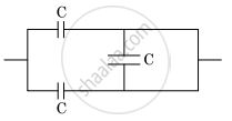
The equivalent capacitance of the combination shown in the figure is ______.
Two charges q1 and q2 are placed at (0, 0, d) and (0, 0, – d) respectively. Find locus of points where the potential a zero.
The total charge on the system of capacitors C1 = 1 µF, C2 = 2 µF, C3 = 4 µF and C4 = 3 µF connected in parallel is ______. (Assume a battery of 20 V is connected to the combination)
The capacitors, each of 4 µF are to be connected in such a way that the effective capacitance of the combination is 6 µF. This can be achieved by connecting ______.
What is the charge relationship for capacitors in series?
Which expressions give the energy stored in series and parallel combinations, respectively?
