Advertisements
Advertisements
प्रश्न
Three capacitors of capacitance `C_1 = 3muf` , `C_2 = 6muf` , `C_3 = 10muf` , are connected to a 10V battery as shown in figure 3 below :
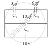
Calculate :
(a) Equivalent capacitance.
(b) Electrostatic potential energy stored in the system
Advertisements
उत्तर
The equivalent capacitance of the series combinationf of `C_1` and `C_2`, is
`C_12 = (C_1.C_2)/(C_1+C_2)`
= `(3 xx 6)/((3 + 6)) muF = 2muF`
This is in parallel with `C_3`.
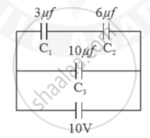
(a) So the equivalent capacitance of the combination of all the three capacitors, is
`C_(eq) = C_12 + C_3 = (2 + 10) = 12muF`
(b) Electrostatic PE stored in the system, is
`E = 1/2 C_(eq) . V^2`
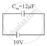
= `1/2 xx 12muF xx (10V)^2 = 600muJ = 6 xx 10^-4 "J"`
APPEARS IN
संबंधित प्रश्न
Two capacitors of unknown capacitances C1 and C2 are connected first in series and then in parallel across a battery of 100 V. If the energy stored in the two combinations is 0.045 J and 0.25 J respectively, determine the value of C1 and C2. Also calculate the charge on each capacitor in parallel combination.
A parallel-plate capacitor has plates of unequal area. The larger plate is connected to the positive terminal of the battery and the smaller plate to its negative terminal. Let Q, and Q be the charges appearing on the positive and negative plates respectively.
Each plate of a parallel plate capacitor has a charge q on it. The capacitor is now connected to a batter. Now,
(a) the facing surfaces of the capacitor have equal and opposite charges
(b) the two plates of the capacitor have equal and opposite charges
(c) the battery supplies equal and opposite charges to the two plates
(d) the outer surfaces of the plates have equal charges
A parallel-plate capacitor is connected to a battery. A metal sheet of negligible thickness is placed between the plates. The sheet remains parallel to the plates of the capacitor.
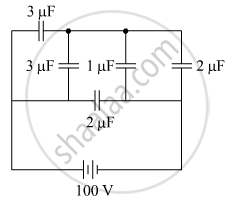
The figure shows a network of five capacitors connected to a 100 V supply. Calculate the total energy stored in the network.
In the circuit shown in figure, initially K1 is closed and K2 is open. What are the charges on each capacitors.
Then K1 was opened and K2 was closed (order is important), What will be the charge on each capacitor now? [C = 1µF]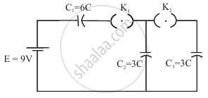
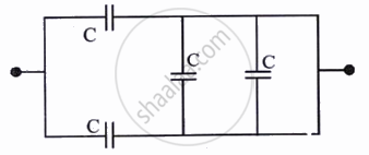
The equivalent capacitance of the combination shown is:
In a series combination, which capacitor has the larger voltage drop?
How is the total charge related to the charges on capacitors in parallel?
A charge of \[1.6\times10^{-11}\,\mathrm{C}\] produces a potential difference of \[10\,\mathrm{V}\]. What capacitance follows from \[C=\frac{Q}{V}\]?
