Advertisements
Advertisements
प्रश्न
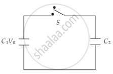
A capacitor of capacity C1 is charged to the potential of V0. On disconnecting with the battery, it is connected with an uncharged capacitor of capacity C2 as shown in the adjoining figure. Find the ratio of energies before and after the connection of switch S.
Advertisements
उत्तर

Before the connection of switch S,
Initial energy `U_i = 1/2C_1V_0^2 + 1/2C_2O^2 = 1/2C_1V_0^2`
After the connection of switch S,
common potential V = `(C_1V_1 + C_2V_2)/(C_1 + C_2) = (C_1V_0)/(C_1 + C_2)`
Final energy = `U_f = 1/2(C_1 + C_2) (C_1V_0)^2/(C_1 + C_2)^2 = 1/2 (C_1^2V_0^2)/((C_1 + C_2))`
`U_f : U_i = C_1/((C_1 + C_2))`
APPEARS IN
संबंधित प्रश्न
Suppose a charge +Q1 is given to the positive plate and a charge −Q2 to the negative plate of a capacitor. What is the "charge on the capacitor"?
A parallel-plate capacitor having plate area 25 cm2 and separation 1⋅00 mm is connected to a battery of 6⋅0 V. Calculate the charge flown through the battery. How much work has been done by the battery during the process?
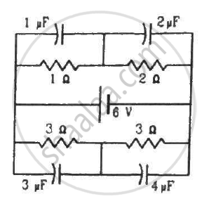
Find the charges on the four capacitors of capacitances 1 μF, 2 μF, 3 μF and 4 μF shown in the figure.
Three capacitors of capacitance `C_1 = 3muf` , `C_2 = 6muf` , `C_3 = 10muf` , are connected to a 10V battery as shown in figure 3 below :
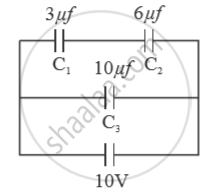
Calculate :
(a) Equivalent capacitance.
(b) Electrostatic potential energy stored in the system
A wire of resistance ‘R’ is cut into ‘n’ equal parts. These parts are then connected in parallel with each other. The equivalent resistance of the combination is:
Capacitors connected in series have ______
Two charges q1 and q2 are placed at (0, 0, d) and (0, 0, – d) respectively. Find locus of points where the potential a zero.
Two equal capacitors are first connected in series and then in parallel The ratio of the equivalent capacities in the two cases will be ______.
Three capacitors of capacitances 2 pF, 3 pF and 4 pF are connected in parallel. What is the total capacitance of the combination?
