Advertisements
Advertisements
Question
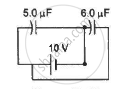
Find the charge supplied by the battery in the arrangement shown in figure.
Advertisements
Solution
The equivalent circuit for the given case can be drawn as :-
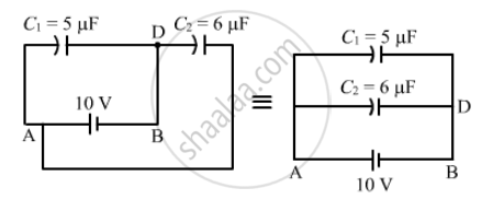
It can be observed that capacitors C1 and C2 are in parallel.
Therefore, the equivalent capacitance is given by
Ceq = C1 + C2
= 5 + 6 = 11 μF
Now ,
Charge supplied by the battery = (Ceq)(V) = (11 μF) × (10 V) = 110 μC
APPEARS IN
RELATED QUESTIONS
A capacitor of capacitance ‘C’ is charged to ‘V’ volts by a battery. After some time the battery is disconnected and the distance between the plates is doubled. Now a slab of dielectric constant, 1 < k < 2, is introduced to fill the space between the plates. How will the following be affected? (a) The electric field between the plates of the capacitor Justify your answer by writing the necessary expressions.
A spherical capacitor has an inner sphere of radius 12 cm and an outer sphere of radius 13 cm. The outer sphere is earthed and the inner sphere is given a charge of 2.5 µC. The space between the concentric spheres is filled with a liquid of dielectric constant 32.
(a) Determine the capacitance of the capacitor.
(b) What is the potential of the inner sphere?
(c) Compare the capacitance of this capacitor with that of an isolated sphere of radius 12 cm. Explain why the latter is much smaller.
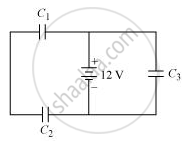
Three identical capacitors C1, C2 and C3 of capacitance 6 μF each are connected to a 12 V battery as shown.
Find
(i) charge on each capacitor
(ii) equivalent capacitance of the network
(iii) energy stored in the network of capacitors
Two capacitors each having capacitance C and breakdown voltage V are joined in series. The capacitance and the breakdown voltage of the combination will be
Two metal spheres of capacitance C1 and C2 carry some charges. They are put in contact and then separated. The final charges Q1 and Q2 on them will satisfy
A parallel-plate capacitor has plate area 25⋅0 cm2 and a separation of 2⋅00 mm between the plates. The capacitor is connected to a battery of 12⋅0 V. (a) Find the charge on the capacitor. (b) The plate separation is decreased to 1⋅00 mm. Find the extra charge given by the battery to the positive plate.
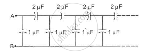
Find the equivalent capacitance of the infinite ladder shown in figure between the points A and B.
The separation between the plates of a parallel-plate capacitor is 0⋅500 cm and its plate area is 100 cm2. A 0⋅400 cm thick metal plate is inserted into the gap with its faces parallel to the plates. Show that the capacitance of the assembly is independent of the position of the metal plate within the gap and find its value.
A parallel-plate capacitor of capacitance 5 µF is connected to a battery of emf 6 V. The separation between the plates is 2 mm. (a) Find the charge on the positive plate. (b) Find the electric field between the plates. (c) A dielectric slab of thickness 1 mm and dielectric constant 5 is inserted into the gap to occupy the lower half of it. Find the capacitance of the new combination. (d) How much charge has flown through the battery after the slab is inserted?
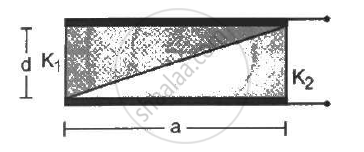
A capacitor is formed by two square metal-plates of edge a, separated by a distance d. Dielectrics of dielectric constant K1 and K2 are filled in the gap as shown in figure . Find the capacitance.
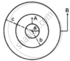
Suppose the space between the two inner shells is filled with a dielectric of dielectric constant K. Find the capacitance of the system between A and B.
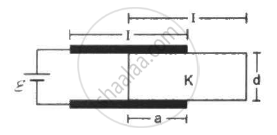
Consider the situation shown in figure. The plates of the capacitor have plate area A and are clamped in the laboratory. The dielectric slab is released from rest with a length a inside the capacitor. Neglecting any effect of friction or gravity, show that the slab will execute periodic motion and find its time period.
The variation of inductive reactance (XL) of an inductor with the frequency (f) of the ac source of 100 V and variable frequency is shown in fig.
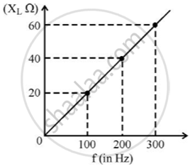
- Calculate the self-inductance of the inductor.
- When this inductor is used in series with a capacitor of unknown value and a resistor of 10 Ω at 300 s–1, maximum power dissipation occurs in the circuit. Calculate the capacitance of the capacitor.
During a thunder storm, the movement of water molecules within the clouds creates friction, partially causing the bottom part of the clouds to become negatively charged. This implies that the bottom of the cloud and the ground act as a parallel plate capacitor. If the electric field between the cloud and ground exceeds the dielectric breakdown of the air (3 × 10⁶ Vm–1), lightning will occur.
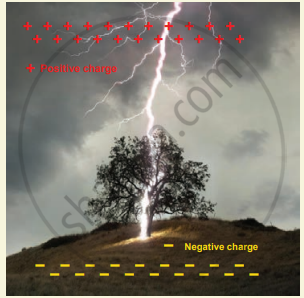
- If the bottom part of the cloud is 1000 m above the ground, determine the electric potential difference that exists between the cloud and ground.
- In a typical lightning phenomenon, around 25 C of electrons are transferred from cloud to ground. How much electrostatic potential energy is transferred to the ground?
A capacitor of capacity 2 µF is charged to a potential difference of 12 V. It is then connected across an inductor of inductance 0.6 mH. The current in the circuit at a time when the potential difference across the capacitor is 6.0 V is ______ × 10-1A.
Which expression gives the capacitance of a capacitor?
In a parallel combination, which statement describes the charges on the capacitors?
Which statement describes the voltage and use of a parallel combination?
