Advertisements
Advertisements
Question
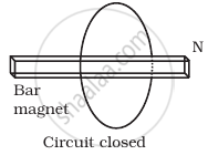
Consider a magnet surrounded by a wire with an on/off switch S (Figure). If the switch is thrown from the off position (open circuit) to the on position (closed circuit), will a current flow in the circuit? Explain.

Advertisements
Solution
Whenever the number of magnetic lines of force (magnetic flux) passing through a circuit changes an emf is produced in the circuit called induced emf. The induced emf persists only as long as there is a change or cutting of flux. The induced emf is given by rate of change of magnetic flux linked with the circuit i.e, `e= (- dphi)/(dt)`. so flux linked will change when either magnetic field, area or the angle between B and A changes.
If the switch is closed, the circuit will complete. But to induce emf in the circuit, we need:
- A changing magnetic field, but the bar magnet is stationary so it is not possible in this situation.
- A changing area is also not possible because area is also constant as coil is not expanding or compressed.
- Angle between B bar and A bar changes, which is also not possible in this situation because orientation of bar magnet and coil is fixed.
Thus, no change in magnetic flux linked with coil occur, hence no electromotive force is induced in the coil and hence no current will flow in the circuit.
APPEARS IN
RELATED QUESTIONS
Use Lenz’s law to determine the direction of induced current in the situation described by the figure:
A wire of irregular shape turning into a circular shape.

Show that Lenz's law is a consequence of conservation of energy.
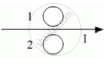
Predict the directions of induced currents in metal rings 1 and 2 lying in the same plane where current I in the wire is increasing steadily.
A bar magnet is moved in the direction indicated by the arrow between two coils PQ and CD. Predict the directions of induced current in each coil.

Explain, with the help of a suitable example, how we can show that Lenz's law is a consequence of the principle of conservation of energy.
For a coil having L = 2 mH, current flows at the rate of 10-3 AIS. The e.m.f induced is
Lenz's law gives ______
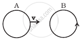
There are two coils A and B as shown in figure. A current starts flowing in B as shown, when A is moved towards B and stops when A stops moving. The current in A is counterclockwise. B is kept stationary when A moves. We can infer that ______.
A solenoid is connected to a battery so that a steady current flows through it. If an iron core is inserted into the solenoid, will the current increase or decrease? Explain.
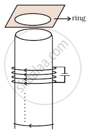
Consider a metal ring kept on top of a fixed solenoid (say on a carboard) (Figure). The centre of the ring coincides with the axis of the solenoid. If the current is suddenly switched on, the metal ring jumps up. Explain

Consider a metal ring kept (supported by a cardboard) on top of a fixed solenoid carrying a current I (Figure). The centre of the ring coincides with the axis of the solenoid. If the current in the solenoid is switched off, what will happen to the ring?
Predict the direction of induced current in the situation described by the following figure.

Use Lenz’s law to determine the direction of induced current in the situation described by the figure.
A circular loop being deformed into a narrow straight wire.

Who formulated Lenz's law in 1834?
What is observed when the magnet is held stationary near the coil?
When the N-pole moves away from the coil, which induced current direction and near-face pole are observed?
What would happen to the magnet if an induced South pole attracted an approaching N-pole without external effort?
A rectangular loop moves into a region where the magnetic field points out of the page. What happens to the flux through the loop?
For a rectangular loop entering an out-of-page magnetic field, what is the induced current direction and path?
