Advertisements
Advertisements
Question
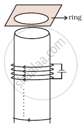
Consider a metal ring kept (supported by a cardboard) on top of a fixed solenoid carrying a current I (Figure). The centre of the ring coincides with the axis of the solenoid. If the current in the solenoid is switched off, what will happen to the ring?
Advertisements
Solution
This problem is based on Lenz’s law and according to this law, the direction of induced emf or current in a circuit is such as to oppose the cause that produces it.
When the switch is opened, current in the circuit of solenoid stops flowing. Initially, there is some magnetic flux linked with the solenoid and now if current in the circuit stops, the magnetic flux falls to zero or we can say that magnetic flux linked through the ring decreases.
According to Lenz’s law, this decrease in flux will be opposed and the ring experiences downward force toward the solenoid.
This happen because the current decrease will cause a clockwise current (as seen from the top in the ring in figure) to increase the decreasing flux. This can be done if the direction of induced magnetic field is same as that of solenoid. This makes the opposite sense of the flow of current in the ring (when viewed from the bottom of the ring) and solenoid form opposite magnetic poles in front of each other.
Hence, they will -attract each other but as ring is placed at the cardboard it could not be able to move downward.
APPEARS IN
RELATED QUESTIONS
State Lenz's law. Illustrate, by giving an example, how this law helps in predicting the direction of the current in a loop in the presence of a changing magnetic flux.
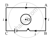
Predict the direction of induced current in the situation described by the following figure.

Predict the direction of induced current in a metal ring when the ring is moved towards a straight conductor with constant speed v. The conductor is carrying current I in the direction shown in the figure.
A bar magnet is moved in the direction indicated by the arrow between two coils PQ and CD. Predict the directions of induced current in each coil.

Two circular loops of equal radii are placed coaxially at some separation. The first is cut and a battery is inserted in between to drive a current in it. The current changes slightly because of the variation in resistance with temperature. During this period, the two loops _______________ .
Consider the situation shown in figure. If the closed loop is completely enclosed in the circuit containing the switch, the closed loop will show _______________ .
Explain, with the help of a suitable example, how we can show that Lenz's law is a consequence of the principle of conservation of energy.
Which of the following statements is not correct?
Young's modulus for aluminium is 7 × 10¹⁰ Pa. The force needed to stretch an aluminium wire of diameter 2 mm and length 800 mm by 1 mm is ______.
A bar magnet is dropped through a copper ring acceleration of magnet is
Energy dissipate in LCR circuit in
Lenz's law gives ______
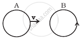
There are two coils A and B as shown in figure. A current starts flowing in B as shown, when A is moved towards B and stops when A stops moving. The current in A is counterclockwise. B is kept stationary when A moves. We can infer that ______.
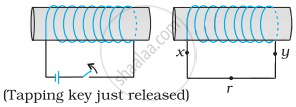
A wire in the form of a tightly wound solenoid is connected to a DC source, and carries a current. If the coil is stretched so that there are gaps between successive elements of the spiral coil, will the current increase or decrease? Explain.
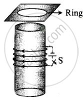
Consider a metal ring kept on top of a fixed solenoid (say on a carboard) (Figure). The centre of the ring coincides with the axis of the solenoid. If the current is suddenly switched on, the metal ring jumps up. Explain

A conducting wire XY of mass m and neglibile resistance slides smoothly on two parallel conducting wires as shown in figure. The closed circuit has a resistance R due to AC. AB and CD are perfect conductors. There is a ˆ. magnetic field `B = B(t)hatk`.
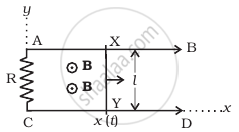
- Write down equation for the acceleration of the wire XY.
- If B is independent of time, obtain v(t) , assuming v(0) = u0.
- For (b), show that the decrease in kinetic energy of XY equals the heat lost in R.
Predict the direction of induced current in the situation described by the following figure.

Predict the direction of induced current in the situation described by the following figure.
Use Lenz’s law to determine the direction of induced current in the situation described by the figure.
A circular loop being deformed into a narrow straight wire.

