Advertisements
Advertisements
Question
A storage battery of emf 8.0 V and internal resistance 0.5 Ω is being charged by a 120 V dc supply using a series resistor of 15.5 Ω. What is the terminal voltage of the battery during charging? What is the purpose of having a series resistor in the charging circuit?
Advertisements
Solution

Emf of the storage battery, E = 8.0 V
Internal resistance of the battery, r = 0.5 Ω
DC supply voltage, V = 120 V
Resistance of the resistor, R = 15.5 Ω
Effective voltage in the circuit = V1
R is connected to the storage battery in series. Hence, it can be written as
V1 = V − E
V1 = 120 − 8
= 112 V
Current flowing in the circuit = I, which is given by the relation,
I = `V_1/(R + r)`
= `112/(15.5 + 5)`
= `112/16`
= 7 A
Voltage across resistor R given by the product, IR = 7 × 15.5
= 108.5 V
DC supply voltage = Terminal voltage of battery + Voltage drop across R
Terminal voltage of battery = 120 − 108.5
= 11.5 V
A series resistor in a charging circuit limits the current drawn from the external source. The current will be extremely high in its absence. This is very dangerous.
RELATED QUESTIONS
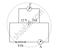
A battery of emf 12 V and internal resistance 2 Ω is connected to a 4 Ω resistor as shown in the figure.
(a) Show that a voltmeter when placed across the cell and across the resistor, in turn, gives the same reading.
(b) To record the voltage and the current in the circuit, why is voltmeter placed in parallel and ammeter in series in the circuit?
Six lead-acid types of secondary cells each of emf 2.0 V and internal resistance 0.015 Ω are joined in series to provide a supply to a resistance of 8.5 Ω. What are the current drawn from the supply and its terminal voltage?
Nichrome and copper wires of same length and same radius are connected in series. Current I is passed through them. Which wire gets heated up more? Justify your answer.
The equivalent resistance between points. a and f of the network shown in Figure 2 is :
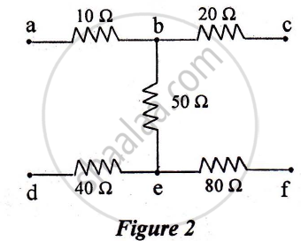
a) 24 Ω
b) 110 Ω
c) 140 Ω
d) 200 Ω
A cell of emf ‘E’ and internal resistance ‘r’ is connected across a variable resistor ‘R’. Plot a graph showing the variation of terminal potential ‘V’ with resistance R. Predict from the graph the condition under which ‘V’ becomes equal to ‘E’.
Can the potential difference across a battery be greater than its emf?
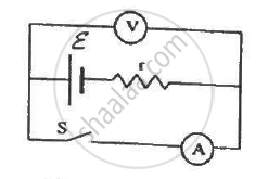
The following figure shows an arrangement to measure the emf ε and internal resistance r of a battery. The voltmeter has a very high resistance and the ammeter also has some resistance. The voltmeter reads 1.52 V when the switch S is open. When the switch is closed, the voltmeter reading drops to 1.45 V and the ammeter reads 1.0 A. Find the emf and the internal resistance of the battery.
Do all thermocouples have a neutral temperature?
The temperatures of the junctions of a bismuth-silver thermocouple are maintained at 0°C and 0.001°C. Find the thermo-emf (Seebeck emf) developed. For bismuth-silver, a = − 46 × 10−6 V°C−1 and b = −0.48 × 10⁻⁶ V°C−2.
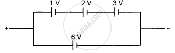
Find the emf of the battery shown in the figure:
If n cells each of emf e and internal resistance r are connected in parallel, then the total emf and internal resistance will be ______.
The internal resistance of a cell is the resistance of ______
A block of metal is heated directly by dissipating power in the internal resistance of block. Because of temperature rise, the resistance increases exponentially with time and is given by R(t) = 0.5 e2t, where t is in second. The block is connected across a 110 V source and dissipates 7644 J heat energy over a certain period of time. This period of time is ______ × 10-1 sec (take ln 0.367 = -1).
A cell of emf E is connected across an external resistance R. When current 'I' is drawn from the cell, the potential difference across the electrodes of the cell drops to V. The internal resistance 'r' of the cell is ______.
Three cells, each of emf E but internal resistances 2r, 3r and 6r are connected in parallel across a resistor R.
Obtain expressions for (i) current flowing in the circuit, and (ii) the terminal potential differences across the equivalent cell.
Study the two circuits shown in the figure below. The cells in the two circuits are identical to each other. The resistance of the load resistor R is the same in both circuits.

If the same current flows through the resistor R in both circuits, calculate the internal resistance of each cell in terms of the resistance of resistor R. Show your calculations.
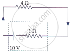
The terminal voltage of the battery, whose emf is 10 V and internal resistance 1 Ω, when connected through an external resistance of 4 Ω as shown in the figure is: