Advertisements
Advertisements
Question
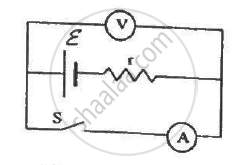
The following figure shows an arrangement to measure the emf ε and internal resistance r of a battery. The voltmeter has a very high resistance and the ammeter also has some resistance. The voltmeter reads 1.52 V when the switch S is open. When the switch is closed, the voltmeter reading drops to 1.45 V and the ammeter reads 1.0 A. Find the emf and the internal resistance of the battery.
Advertisements
Solution
(a) 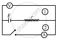
When the switch S is opened, loop 2 will be open and no current will pass through the ammeter. Loop 1 will be closed; so, a current will flow through it. But since the voltmeter has very high resistance, compared to the internal resistance of the battery, the voltage-drop across the internal resistance can be ignored, compared to the voltage drop across the voltmeter. So, the voltage appearing across the voltmeter will be almost equal to the emf of the battery.
∴ ε = 1.52 V
(b) When the switch is closed, current will pass through the circuit in loop 2. In this case, there will be a voltage drop across r due to current i flowing through it.
Applying the loop rule, we get:-
ε – ir = 1.45
⇒ 1.52 – ir = 1.45
⇒ ir = 0.07
⇒ 1.r = 0.07
r = 0.07 Ω
APPEARS IN
RELATED QUESTIONS
A storage battery of emf 8.0 V and internal resistance 0.5 Ω is being charged by a 120 V dc supply using a series resistor of 15.5 Ω. What is the terminal voltage of the battery during charging? What is the purpose of having a series resistor in the charging circuit?
Six lead-acid types of secondary cells each of emf 2.0 V and internal resistance 0.015 Ω are joined in series to provide a supply to a resistance of 8.5 Ω. What are the current drawn from the supply and its terminal voltage?
A secondary cell after long use has an emf of 1.9 V and a large internal resistance of 380 Ω. What maximum current can be drawn from the cell? Could the cell drive the starting motor of a car?
A long straight current carrying wire passes normally through the centre of circular loop. If the current through the wire increases, will there be an induced emf in the loop? Justify.
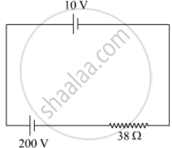
A 10 V cell of negligible internal resistance is connected in parallel across a battery of emf 200 V and internal resistance 38 Ω as shown in the figure. Find the value of current in the circuit.
In a potentiometer arrangement for determining the emf of a cell, the balance point of the cell in open circuit is 350 cm. When a resistance of 9 Ω is used in the external circuit of the cell, the balance point shifts to 300 cm. Determine the internal resistance of the cell.
A resistor R is connected to a cell of-emf e and internal resistance r. The potential difference across the resistor R is found to be V. State the relation between e, V, Rand r.
A cell of emf ‘E’ and internal resistance ‘r’ draws a current ‘I’. Write the relation between terminal voltage ‘V’ in terms of E, I and r ?
Two identical cells, each of emf E, having negligible internal resistance, are connected in parallel with each other across an external resistance R. What is the current through this resistance?
A cell of emf ‘E’ and internal resistance ‘r’ is connected across a variable resistor ‘R’. Plot a graph showing the variation of terminal potential ‘V’ with resistance R. Predict from the graph the condition under which ‘V’ becomes equal to ‘E’.
Consider N = n1n2 identical cells, each of emf ε and internal resistance r. Suppose n1 cells are joined in series to form a line and n2 such lines are connected in parallel.
The combination drives a current in an external resistance R. (a) Find the current in the external resistance. (b) Assuming that n1 and n2 can be continuously varied, find the relation between n1, n2, R and r for which the current in R is maximum.
A battery of emf 100 V and a resistor of resistance 10 kΩ are joined in series. This system is used as a source to supply current to an external resistance R. If R is not greater than 100 Ω, the current through it is constant up to two significant digits.
Find its value. This is the basic principle of a constant-current source.
How many time constants will elapse before the power delivered by a battery drops to half of its maximum value in an RC circuit?
The temperatures of the junctions of a bismuth-silver thermocouple are maintained at 0°C and 0.001°C. Find the thermo-emf (Seebeck emf) developed. For bismuth-silver, a = − 46 × 10−6 V°C−1 and b = −0.48 × 10⁻⁶ V°C−2.
Two cells of emfs approximately 5 V and 10 V are to be accurately compared using a potentiometer of length 400 cm.
A cell having an emf E and internal resistance r is connected across a variable external resistance R. As the resistance R is increased, the plot of potential difference V across R is given by ______.
Five cells each of emf E and internal resistance r send the same amount of current through an external resistance R whether the cells are connected in parallel or in series. Then the ratio `("R"/"r")` is:
