Advertisements
Advertisements
Question
A plate of area 10 cm2 is to be electroplated with copper (density 9000 kg m−3) to a thickness of 10 micrometres on both sides, using a cell of 12 V. Calculate the energy spent by the cell in the process of deposition. If this energy is used to heat 100 g of water, calculate the rise in the temperature of the water. ECE of copper = 3 × 10⁻⁷ kg C−1and specific heat capacity of water = 4200 J kg−1.
Advertisements
Solution
Surface area of the plate, A = 10 cm2 = 10 × 10−4 m2
Thickness of copper deposited, t = 10 μm = 10−5 m
Density of copper = 9000 kg/m3
Volume of copper deposited, V = A(2t)
V = 10 × 10−4 × 2 × 10 × 10−6
= 2 × 102 × 10−10
= 2 × 10⁻⁸ m3
Mass of copper deposited, m = Volume × Density = 2 × 10−8 × 9000
⇒ m = 18 × 10−5 kg
Using the formula, m = ZQ, we get:-
18 × 10−5 = 3 × 10⁻⁷ × Q
⇒ Q = 6 × 10² C
Energy spent by the cell = Work done by the cell
⇒W = VQ
= 12 × 6 × 102
= 72 × 102 = 7.2 kJ
Let ∆θ be the rise in temperature of water. When this energy is used to heat 100 g of water, we have:-
7.2 × 103 = 100 × 10−3 × 4200 × ∆θ
⇒ ∆θ = 17 K
APPEARS IN
RELATED QUESTIONS
Two cells of emfs 1.5 V and 2.0 V, having internal resistances 0.2 Ω and 0.3 Ω, respectively, are connected in parallel. Calculate the emf and internal resistance of the equivalent cell.
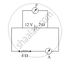
A battery of emf 12 V and internal resistance 2 Ω is connected to a 4 Ω resistor as shown in the figure.
(a) Show that a voltmeter when placed across the cell and across the resistor, in turn, gives the same reading.
(b) To record the voltage and the current in the circuit, why is voltmeter placed in parallel and ammeter in series in the circuit?
A secondary cell after long use has an emf of 1.9 V and a large internal resistance of 380 Ω. What maximum current can be drawn from the cell? Could the cell drive the starting motor of a car?
Nichrome and copper wires of same length and same radius are connected in series. Current I is passed through them. Which wire gets heated up more? Justify your answer.
The equivalent resistance between points. a and f of the network shown in Figure 2 is :
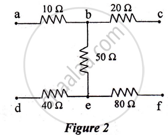
a) 24 Ω
b) 110 Ω
c) 140 Ω
d) 200 Ω
Can the potential difference across a battery be greater than its emf?
Two non-ideal batteries are connected in series. Consider the following statements:-
(A) The equivalent emf is larger than either of the two emfs.
(B) The equivalent internal resistance is smaller than either of the two internal resistances.
Two non-ideal batteries are connected in parallel. Consider the following statements:-
(A) The equivalent emf is smaller than either of the two emfs.
(B) The equivalent internal resistance is smaller than either of the two internal resistances.
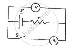
The following figure shows an arrangement to measure the emf ε and internal resistance r of a battery. The voltmeter has a very high resistance and the ammeter also has some resistance. The voltmeter reads 1.52 V when the switch S is open. When the switch is closed, the voltmeter reading drops to 1.45 V and the ammeter reads 1.0 A. Find the emf and the internal resistance of the battery.
Consider N = n1n2 identical cells, each of emf ε and internal resistance r. Suppose n1 cells are joined in series to form a line and n2 such lines are connected in parallel.
The combination drives a current in an external resistance R. (a) Find the current in the external resistance. (b) Assuming that n1 and n2 can be continuously varied, find the relation between n1, n2, R and r for which the current in R is maximum.
Apply the first law of thermodynamics to a resistor carrying a current i. Identify which of the quantities ∆Q, ∆U and ∆W are zero, positive and negative.
A coil of resistance 100 Ω is connected across a battery of emf 6.0 V. Assume that the heat developed in the coil is used to raise its temperature. If the heat capacity of the coil is 4.0 J K−1, how long will it take to raise the temperature of the coil by 15°C?
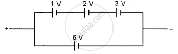
Find the emf of the battery shown in the figure:
A straight line plot showing the terminal potential difference (V) of a cell as a function of current (I) drawn from it, is shown in the figure. The internal resistance of the cell would be then ______.

The internal resistance of a cell is the resistance of ______
Three cells, each of emf E but internal resistances 2r, 3r and 6r are connected in parallel across a resistor R.
Obtain expressions for (i) current flowing in the circuit, and (ii) the terminal potential differences across the equivalent cell.
An ac generator generates an emf which is given by e = 311 sin (240 πt) V. Calculate:
- frequency of the emf.
- r.m.s. value of the emf.
A wire of length ‘l’ and resistance 100 Ω is divided into 10 equal parts. The first 5 parts are connected in series while the next 5 parts are connected in parallel. The two combinations are again connected in series. The resistance of this final combination is ______.
