Please select a subject first
Advertisements
Advertisements
Write current sensitivity of a galvanomete S.I. unit.
Concept: Moving Coil Galvanometer
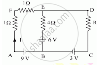
Using Kirchhoff’s rules determine the value of unknown resistance R in the circuit so that no current flows through 4 Ω resistance. Also find the potential difference between A and D.
Concept: Kirchhoff’s Laws
Read the following paragraph and answer the questions.
|
Consider the experimental set-up shown in the figure. This jumping ring experiment is an outstanding demonstration of some simple laws of Physics. A conducting non-magnetic ring is placed over the vertical core of a solenoid. When current is passed through the solenoid, the ring is thrown off. |

- Explain the reason for the jumping of the ring when the switch is closed in the circuit.
- What will happen if the terminals of the battery are reversed and the switch is closed? Explain.
- Explain the two laws that help us understand this phenomenon.
Concept: Ampere’s Circuital Law
- Assertion (A): The deflecting torque acting on a current-carrying loop is zero when its plane is perpendicular to the direction of the magnetic field.
- Reason (R): The deflecting torque acting on a loop of the magnetic moment `vecm` in a magnetic field `vecB` is given by the dot product of `vecm` and `vecB`.
Concept: Torque on a Rectangular Current Loop in a Uniform Magnetic Field
A galvanometer shows full-scale deflection for current Ig. A resistance R1 is required to convert it into a voltmeter of range (0 - V) and a resistance R2 to convert it into a voltmeter of range (0 - 2V). Find the resistance of the galvanometer.
Concept: Moving Coil Galvanometer
Briefly explain various ways to increase the strength of the magnetic field produced by a given solenoid.
Concept: Ampere’s Circuital Law
Out of the two magnetic materials, 'A' has relative permeability slightly greater than unity while 'B' has less than unity. Identify the nature of the materials 'A' and 'B'. Will their susceptibilities be positive or negative?
Concept: Magnetic Properties of Materials
Show diagrammatically the behaviour of magnetic field lines in the presence of (i) paramagnetic and (ii) diamagnetic substances. How does one explain this distinguishing feature?
Concept: Magnetic Properties of Materials
In an experiment, two coils c1 and c2 are placed close to each other. Find out the expression for the emf induced in the coil c1 due to a change in the current through the coil c2.
Concept: Inductance >> Mutual Inductance
Describe a simple experiment (or activity) to show that the polarity of emf induced in a coil is always such that it tends to produce a current which opposes the change of magnetic flux that produces it.
Concept: Lenz’s Law and Conservation of Energy
The current flowing through an inductor of self inductance L is continuously increasing. Plot a graph showing the variation of
Magnetic flux versus the current
Concept: Magnetic Flux
The current flowing through an inductor of self inductance L is continuously increasing. Plot a graph showing the variation of Magnetic potential energy stored versus the current.
Concept: Inductance >> Mutual Inductance
Draw a schematic sketch of an ac generator describing its basic elements. State briefly its working principle. Show a plot of variation of
(i) Magnetic flux and
(ii) Alternating emf versus time generated by a loop of wire rotating in a magnetic field.
Concept: Magnetic Flux
How does the mutual inductance of a pair of coils change when
(i) distance between the coils is increased and
(ii) number of turns in the coils is increased?
Concept: Magnetic Flux
Welders wear special goggles or face masks with glass windows to protect their eyes from electromagnetic radiations. Name the radiations and write the range of their frequency.
Concept: Introduction to Electromagnetic Induction
Calculate the self-inductance of a coil using the following data obtained when an AC source of frequency `(200/pi)` Hz and a DC source are applied across the coil.
| AC Source | ||
| S.No. | V (volts) | I (A) |
| 1 | 3.0 | 0.5 |
| 2 | 6.0 | 1.0 |
| 3 | 9.0 | 1.5 |
| DC Source | ||
| S.No. | V (volts) | I (A) |
| 1 | 4.0 | 1.0 |
| 2 | 6.0 | 1.5 |
| 3 | 8.0 | 2.0 |
Concept: Inductance >> Self Inductance
A group of students while coming from the school noticed a box marked "Danger H.T. 2200 V" at a substation in the main street. They did not understand the utility of a such a high voltage, while they argued, the supply was only 220 V. They asked their teacher this question the next day. The teacher thought it to be an important question and therefore explained to the whole class.
Answer the following questions:
(i) What device is used to bring the high voltage down to low voltage of a.c. current and what is the principle of its working ?
(ii) Is it possible to use this device for bringing down the high dc voltage to the low voltage? Explain
(iii) Write the values displayed by the students and the teacher.
Concept: Transformers
A voltage V = V0 sin ωt is applied to a series LCR circuit. Derive the expression for the average power dissipated over a cycle. Under what condition (i) no power is dissipated even though the current flows through the circuit, (ii) maximum power is dissipated in the circuit?
Concept: AC Voltage Applied to a Series LCR Circuit
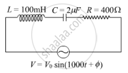
(i) Find the value of the phase difference between the current and the voltage in the series LCR circuit shown below. Which one leads in phase : current or voltage ?
(ii) Without making any other change, find the value of the additional capacitor C1, to be connected in parallel with the capacitor C, in order to make the power factor of the circuit unity.
Concept: AC Voltage Applied to a Series LCR Circuit
A power transmission line feeds input power at 2200 V to a step-down transformer with its primary windings having 300 turns. Find the number of turns in the secondary to get the power output at 220 V.
Concept: Transformers
