Advertisements
Advertisements
Question
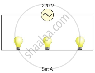
(i) Two sets A and B, of three bulbs each, are glowing in two separate rooms. When one of the bulbs in set A is fused, the other two bulbs also cease to glow. But in set B, when one bulb fuses, the other two bulbs continue to glow. Explain why this phenomenon occurs.
(ii) Why do we prefer arrangements of Set B for house circuiting?
Advertisements
Solution
In set A, all the three bulbs are connected in series. The voltage of source gets divided in all the three bulbs connected in series, and they operate simultaneously. None of the bulb can be operated independently, and hence when one bulb fuses the other two bulbs also cease to glow.
In set B, the three bulbs are connected in parallel. So, even when one of the bulbs ceases to glow, the others continue to glow. Each bulb operates independently.
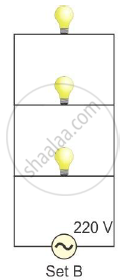
For house circuiting we use the set B arrangement i.e., all the appliances are connected in parallel. The advantage of connecting the appliances in parallel are:
1. Each appliance gets connected to 220 V supply for its normal working.
2. Each appliance works independently without being affected whether the other appliance is switched on or off.
Whereas when connected in series
- All appliances that are connected operate simultaneously and none can be operated independently.
- Voltage of the source gets divided and on connecting one more appliance in the same circuit, the resistance of the circuit will increase. Hence, it will reduce the current in the circuit, so each appliance will get less power.
Hence we prefer arrangements of set B for house circuiting.
APPEARS IN
RELATED QUESTIONS
A battery of 9 V is connected in series with resistors of 0.2 Ω, 0.3 Ω, 0.4 Ω, 0.5 Ω and 12 Ω, respectively. How much current would flow through the 12 Ω resistor?
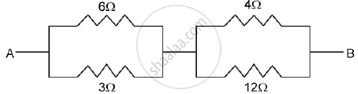
Find the equivalent resistance between A and B
State how are the two resistors joined with a battery when equivalent resistance is more than either of the two resistances.
Name the following substances:
(i) Showing low resistivity,
(ii) Showing very high resistivity,
(iii) Showing moderate resistivity.
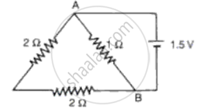
What is the equivalent resistance between A and B in the given circuit (Fig?)
How does the resistivity of an alloy such as constantace depends on temperature.
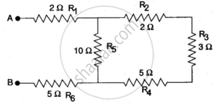
Six resistances are connected together as shown in the figure. Calculate the equivalent resistance between points A and B.
Illustrate-combination of cells e.g., three cells, in series, explaining the combination briefly. Obtain an expression for current ‘i’ in the combination.
With the help of a circuit diagram derive the formula for the resultant resistance of three resistances connected:
- in series and
- in parallel
