English

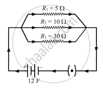
Find the Effective Resistance in the Following Circuit Diagrams (Fig.):

Advertisements
Advertisements

Question

Find the effective resistance in the following circuit diagrams (Fig.):
Numerical
Advertisements

Solution

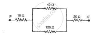
(b) In the given network, the parallel combination of resistors 40 Ω and 120 Ω is connected in series with the 10 Ω and 20 Ω resistors.
:. Resistance in para!! el is:

`1/"R"_"P" = 1/40 + 1/120 = 4/120 = 1/30`

.·. `"R"_"p"` =3Ω

Effective resistance between P and Q is

R = 10 + 30 + 20 = 60 Ω

shaalaa.com
  Is there an error in this question or solution?
Chapter 4: Electricity and Magnetism - Exercise 3 [Page 211]

APPEARS IN

Frank Physics Part 2 [English] Class 10 ICSE
Chapter 4 Electricity and Magnetism
Exercise 3 | Q 1.2 | Page 211

RELATED QUESTIONS

Draw the electrical symbols of the following components and state its use

Wire crossing


An electric circuit consisting of a 0.5 m long nichrome wire XY, an ammeter, a voltmeter, four cells of 1.5 V each and a plug key was set up.  

Following graph was plotted between V and I values: 


What would be the values of `V/I` rations when the potential difference is 0.8 V, 1.2 V and 1.6 V respectively?
What conclusion do you draw from these values?
 
What is the resistance of the wire? 


State two differences between the e.m.f and terminal voltage of a cell. 


Tick(✓) the correct choice in the following:

24 watt, 12 volt head lamp is fully lit by connecting it to a 12 volt
battery. The working resistance of the lamp is


Two resistors P and Q of the same material and length but of different thickness are connected in parallel to a battery. The cross- sectional area of P is twice that of Q. What is the ratio of
(a) The resistance of P to the resistance of Q?
(b) The current in P to the current in Q?


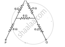
Find the effective resistance in the following circuit diagrams (Fig.):

A 3 pin mains plug is fitted to the lead for a 1 kW electric kettle to be used on a 250 V A.C. supply. Which of the following statements is NOT correct?
(a) A 13 A fuse is the most appropriate value to use.
(b) The brown wire should be connected to the live side of the mains.


Fig . shows the core of a transformer and i ts input and output connections 

State the material used for the core and describe th e structure of the core.
(a) Use the values given in the diagram to calculate the turns ratio for the transformer and connections, labeling all parts of the diagram .
(b) If a current of 2 A is taken from th e output, calculate th e current in the input circuit (Assume the transformer to be ideal ).


The flow of electric charge per unit time is called potential difference.


For current to flow, one needs art open circuit.


Share
Notifications

Englishहिंदीमराठी


      Forgot password?
Use app×