Advertisements
Advertisements
Question
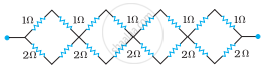
Determine the equivalent resistance of networks shown in Fig.
Advertisements
Solution
It can be observed from the given circuit that in the first small loop, two resistors of resistance 1 Ω each are connected in series.
Hence, their equivalent resistance = (1 + 1) = 2 Ω
It can also be observed that two resistors of resistance 2 Ω each are connected in series.
Hence, their equivalent resistance = (2 + 2) = 4 Ω.
Therefore, the circuit can be redrawn as

It can be observed that 2 Ω and 4 Ω resistors are connected in parallel in all four loops. Hence, equivalent resistance (R’) of each loop is given by,
R' = `(2 xx 4)/(2 + 4)`
= `8/6`
= `4/3` Ω
The circuit reduces to,

All four resistors are connected in series.
Hence, the equivalent resistance of the given circuit is `4/3 xx 4` = `16/3` Ω.
APPEARS IN
RELATED QUESTIONS
Kirchhoff's junction law is equivalent to .............................
(a) conservation of energy.
(b) conservation of charge
(c) conservation of electric potential
(d) conservation of electric flux
Use Kirchhoff's rules to obtain conditions for the balance condition in a Wheatstone bridge.
Given n resistors each of resistance R, how will you combine them to get the (i) maximum (ii) minimum effective resistance? What is the ratio of the maximum to minimum resistance?
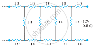
Determine the current drawn from a 12 V supply with internal resistance 0.5 Ω by the infinite network shown in the figure. Each resistor has 1 Ω resistance.
Given the resistances of 1 Ω, 2 Ω, 3 Ω, how will be combine them to get an equivalent resistance of (6/11) Ω?
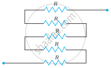
Determine the equivalent resistance of networks shown in Fig.
State Kirchhoff's rules for an electric network. Using Kirchhoff's rules, obtain the balance condition in terms of the resistances of four arms of Wheatstone bridge.
Using Kirchhoff’s rules determine the value of unknown resistance R in the circuit so that no current flows through 4 Ω resistance. Also find the potential difference between A and D.
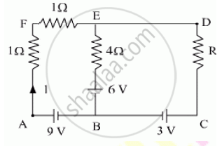
Calculate the value of the resistance R in the circuit shown in the figure so that the current in the circuit is 0.2 A. What would b the potential difference between points B and E?

Consider the following two statements:-
(A) Kirchhoff's junction law follows from conservation of charge.
(B) Kirchhoff's loop law follows from conservative nature of electric field.
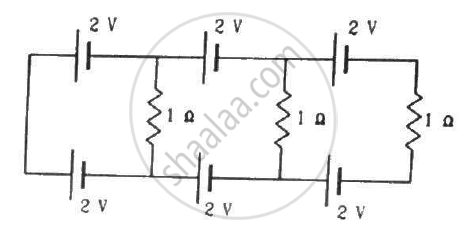
Find the circuit in the three resistors shown in the figure.
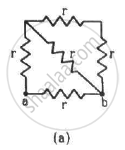
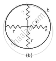
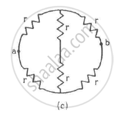
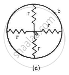
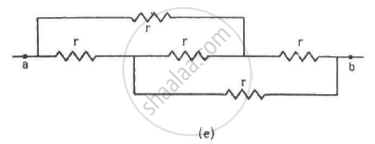
Find the equivalent resistances of the networks shown in the figure between the points a and b.
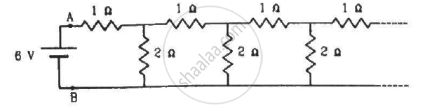
An infinite ladder is constructed with 1 Ω and 2 Ω resistors, as shown in the figure. (a) Find the effective resistance between the points A and B. (b) Find the current that passes through the 2 Ω resistor nearest to the battery.
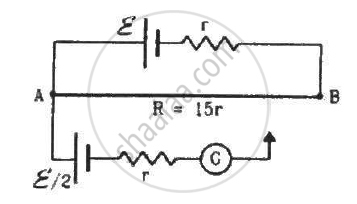
Consider the potentiometer circuit as arranged in the figure. The potentiometer wire is 600 cm long. (a) At what distance from the point A should the jockey touch the wire to get zero deflection in the galvanometer? (b) If the jockey touches the wire at a distance of 560 cm from A, what will be the current in the galvanometer?
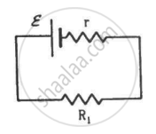
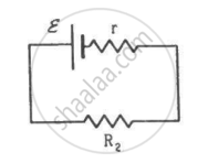
Two unequal resistances, R1 and R2, are connected across two identical batteries of emf ε and internal resistance r (see the figure). Can the thermal energies developed in R1 and R2 be equal in a given time? If yes, what will be the condition?
On which conservation principle is Kirchoff's Second Law of electrical networks based?
Solve the following question.
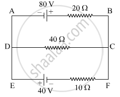
Using Kirchhoff’s rules, calculate the current through the 40 Ω and 20 Ω resistors in the following circuit.
Twelve wires each having a resistance of 3 Ω are connected to form a cubical network. A battery of 10 V and negligible internal resistance is connected across the diagonally opposite corners of this network. Determine its equivalent resistance and the current along each edge of the cube.
State the principle of potentiometer.
State and explain Kirchhoff’s rules.
Obtain the condition for bridge balance in Wheatstone’s bridge.
A copper wire of 10-6 m2 area of cross-section, carries a current of 2 A. If the number of electrons per cubic meter is 8 × 1028, calculate the current density and average drift velocity.
In a potentiometer arrangement, a cell of emf 1.25 V gives a balance point at 35 cm length of the wire. If the cell is replaced by another cell and the balance point shifts to 63 cm, what is the emf of the second cell?
The instrument for the accurate measurement of the e.m.f of a cell is ______.
Assertion: Kirchhoff’s junction rule follows from conservation of charge.
Reason: Kirchhoff’s loop rule follows from conservation of momentum.
The e.m.f of The battery in a thermocouple is doubled. The rate of heat generated at one of the junction will.
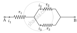
Three resistors having resistances r1, r2 and r3 are connected as shown in the given circuit. The ratio `"i"_3/"i"_1` of currents in terms of resistances used in the circuit is :
Why are alloys used for making standard resistance coils?
A 6-volt battery is connected to the terminals of a three-metre-long wire of uniform thickness and resistance of 100 ohms. The difference of potential between two points on the wire separated by a distance of 50 cm will be ______.
What is a junction or node?
Which term is defined as the rate of flow of charge through a conductor?
After a charge completes one full loop and returns to its starting point, what is the net change in potential?
In a closed loop containing cells and resistors, what equals the total potential drop across the resistors?
While moving in the direction of current through a resistor, how is the potential change treated?
While moving opposite to the direction of current through a resistor, how is the potential change treated?
What is the sign of the emf when moving from the negative terminal to the positive terminal of a cell?
