Advertisements
Online Mock Tests
Chapters
1: Forces: Turning Forces and Uniform Circular Motion
2: Work, Power and Energy
3: Machines
(B) Light
4: Refraction of Light
5: Electromagnetic Waves and Spectrum
(C) Sound
6: Sound
(D) Electricity and Magnetism
7: Electric Circuits, Resistance and Ohm's Law
8: Electric Energy, Power and Household Circuits
▶ 9: 1. Electromagnetism 2. Magnetic Effects of Electric Current 3. Electromagnetic Induction
(E) Heat
Chapter 10: Calorimetry
(F) Modern Physics
Chapter 11: Radioactivity
Advertisements
Solutions for Chapter 9: 1. Electromagnetism 2. Magnetic Effects of Electric Current 3. Electromagnetic Induction
Below listed, you can find solutions for Chapter 9 of CISCE Goyal Brothers Prakashan for अ न्यू अप्रोच टू आईसीएसई [अंग्रेजी] कक्षा १०.
Goyal Brothers Prakashan solutions for अ न्यू अप्रोच टू आईसीएसई [अंग्रेजी] कक्षा १० 9 1. Electromagnetism 2. Magnetic Effects of Electric Current 3. Electromagnetic Induction EXERCISE-1 [Pages 206 - 211]
State the condition when an electric charge can give rise to a magnetic field.
Diagram alongside shows a freely pivoted magnetic needle. A copper conductor is held parallel to the magnetic axis of the needle. In which direction the north pole of needle moves in the following situations:
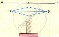
- When the copper conductor is above the magnetic needle and current flows from A to B?
- When the copper conductor is below the magnetic needle and current flows from A to B?
- Why does the magnetic needle move in the situations (i) and (ii)?
- Name and state the law, which helped you to find answer (i) and (ii).
Diagram alongside shows a smooth, but stiff cardboard ABCD, held horizontally, such that a straight thick copper conductor passes through the middle of cardboard. On the cardboard are sprinkled fine iron filings. A current is made to flow through the conductor as shown in diagram.
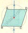
- Copy the diagram and describe what happens to the iron filings? Give an explanation.
- If instead of iron filings, a plotting magnetic compass is used, draw the magnetic line of force produced in diagram and show its direction.
- Name and state two rules by which you can find the direction of magnetic field around the straight conductor carrying current.
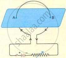
- Copy the adjacent diagram and plot magnetic fields around A and B for the circular coil, when the current flows through it.
- State one way of increasing the magnetic intensity of the circular coil.
- Give two characteristics of the magnetic field produced by the coil.
- What is the direction of magnetic field with respect to the plane of circular coil?
- What polarity (magnetic) is produced on the coil facing you?
What is an electromagnet?
State four ways of measuring the strength of an electromagnet.
State two common uses of electromagnets?
State two advantages of an electromagnet over a bar magnet.
How can you demagnetise a bar magnet by employing alternating current?
A current-carrying solenoid is suspended so as to freely rotate in a horizontal plane. State in what direction will it rest. Give a reason for your answer.
or
When a solenoid that is carrying current is freely suspended, it comes to rest in a particular direction. Why does this happen?
The diagrams (a), (b) and (c) show a smooth, but stiff cardboard, held horizontally, such that a thick copper wire passes through the middle of cardboard. The direction of the current is shown by arrows. Copy the diagrams.
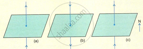
- In the diagrams (a) and (b) show the magnetic field due to conductor, showing at least four magnetic lines force. Assume there is no magnetic field due to earth.
- In the diagram (c) show the magnetic field due to conductor when earth's magnetic field is acting by four magnetic lines of force.
The diagram given below shows a copper wire wound around a U-shaped soft iron bar. An iron pin is brought near the arrangement. First Source P and then Source Q are connected across AB, each operating independently.

(a) State true or false:
Source P as well as Source Q, when connected across AB, can attract the iron pin.
(b) Justify your answer to (a) with a suitable reason.
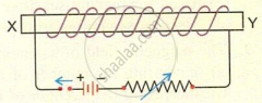
- The figure alongside shows an electromagnet. What is the polarity at the end of X?
- Suggest a way by which the strength of the electromagnet referred to can be measured.
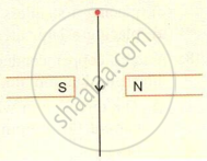
- The diagram alongside shows a freely suspended copper conductor carrying current held in between the pole pieces of a permanent magnet. State whether conductor will move into the plane of paper or out of the plane of paper.
- Why does copper conductor move?
- State the rule which determines motion of conductor.
- State three factors which determine the force acting on conductor.
The diagram shows a rectangular coil ABCD, suspended freely between the concave pole pieces of a permanent horseshoe magnet, such that the plane of the coil is parallel to the magnetic field.
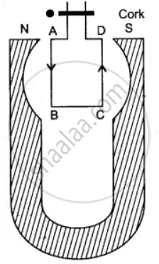
- State your observation when the current is switched on.
- Give an explanation for your observation in (i).
- State the rule, which will help you to find the motion of rotation of the coil.
- In which position will the coil ultimately come to rest?
- State four ways of increasing the magnitude of force acting on the coil.
Draw a labelled diagram of a D.C. motor showing its main parts.
What is the function of radial magnets in a d.c. motor?
What is the function of insulated copper coil in d.c. motor?
What is the function of soft iron core in d.c. motor?
What is the function of the split rings in a d.c. motor?
What is the function of brushes in an electric generator?
State the position of armature coil relative to the direction of magnetic field, in a D. C. motor when the deflecting couple acting an the coil is maximum.
State the position of armature coil relative to the direction of magnetic field, in a D. C. motor when the deflecting couple acting and the coil is minimum.
How is the jerky motion of the coil converted into smooth circular motion?
State three ways of making a motor powerful.
MULTIPLE CHOICE QUESTIONS Choose the most appropriate option.
A wire carrying a current is held over a freely suspended magnetic needle, such that the current in the wire flows from south to north. The direction in which the north end of freely suspended magnetic needle will point towards:
West
East
South
North
In an electric motor:
mechanical energy changes to heat energy
mechanical energy changes to electric energy
electric energy changes to mechanical energy
electric energy changes to magnetic energy
By reversing the direction of the current in an electromagnet, the magnetic field produced by it:
increases in strength
remains unchanged in strength and direction
gets reversed in direction
decreases in strength
The power of a d.c. motor can be increased:
by increasing number of turns in its coil
by laminating its soft iron core
by increasing the strength of current flowing through it.
all of these
Commutator is a device in a d.c. motor which:
increases the power
reverses direction of current coil after full rotation of coil
reverses direction of current after half rotation of coil
increases the strength of electromagnet
Which is not the use of an electromagnet?
Used in electric appliances such as electric bell and electric fans.
Used for magnetising steel bars.
Used for making sensitive magnetic compass.
Used in separating iron particles from a scrap of iron and other metals.
The magnetic field of solenoid can not be increased by:
increasing the number of turns in the solenoid.
increasing the strength of current flowing through the solenoid.
placing a stainless steel core within the solenoid.
placing a laminated soft iron core within the solenoid.
A thick copper conductor is held parallel to a freely pivoted magnetic needle, as shown in the diagram alongside. Answer the question given below:
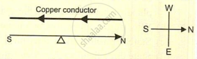
The direction in which the north pole of the pivoted magnetic needle will point when current flows from north to south is:
West
East
Will not get affected
none of these
A thick copper conductor is held parallel to a freely pivoted magnetic needle, as shown in the diagram alongside. Answer the question given below:
If the magnitude of current in the conductor is gradually increased the maximum angle through which magnetic needle will turn is :
90°
45°
60°
none of these
A thick copper conductor is held parallel to a freely pivoted magnetic needle, as shown in the diagram alongside. Answer the question given below:
If the conductor is held below the magnetic needle and parallel to it, then the direction which north pole of pivoted magnetic will point, is:
east
north-east
west
none of these
A thick copper conductor is held parallel to a freely pivoted magnetic needle, as shown in the diagram alongside. Answer the question given below:
The direction of the magnetic field set up by the conductor carrying current is:
always in the direction of the current
always against the direction of the current
always at right angles to the direction of the current
all of these
Which is not the characteristic of the magnetic field set up by a straight conductor carrying current?
Any conductor in which current flows behaves like a magnet.
The direction of magnetic field is in the direction of flow of current
The direction of magnetic field is at right angles to the direction of flow of current
The magnetic intensity increases with the increase in magnitude of current in the conductor.
A straight conductor carrying current passes through a rectangular cardboard as shown in the diagram. The magnetic lines of force around point A are in:
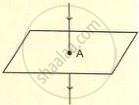
clockwise direction
anticlockwise direction
parallel to the direction of conductor
none of these
The law which helped you to find the direction of magnetic field lines is:
Oerested law
Right hand thumb rule
Maxwell’s Cork screw Rule
both Right hand thumb rule and Maxwell’s Cork screw Rule
Which is the incorrect statement? When a current flows through a conductor,
the conductor has magnetic field around it.
the direction of magnetic field is at right angles to the direction of flow of current
the conductor has electric field around the conductor.
all of these
A conductor carrying current cannot produce electrostatic force because:
The net positive or negative charge on the conductor is zero.
The number of electrons entering the conductor is equal to number of electrons leaving the conductor and hence, in a way conductor is electrically neutral.
Both
- The net positive or negative charge on the conductor is zero.
- The number of electrons entering the conductor is equal to number of electrons leaving the conductor and hence, in a way conductor is electrically neutral.
None of these
Which is not the property of magnetic lines of force around a straight conductor carrying current?
When magnitude of current is low in a conductor the lines of force are parallel to the direction of current.
The magnetic lines of force are in the form of concentric circles.
The plane of magnetic lines of force is always at right angles to the straight conductor carrying current.
The direction of magnetic lines of force reverses with the reversing of the direction of current.
Study the diagram alongside carefully and answer the following question:
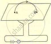
The direction of the magnetic lines of force around A and B will be:
clockwise around both A and B.
anticlockwise around both A and B.
clockwise around A and anticlockwise around B
anticlockwise around A and clockwise around B.
Study the diagram alongside carefully and answer the following question:
The magnetic lines of force within the coil are:
in same direction
in different directions
same direction in middle and clockwise near A and B.
same direction in middle and anticlockwise near A and B.
Study the diagram alongside carefully and answer the following question:
In the coil facing you, the direction of the current is clockwise. Therefore, the face of the coil towards you will have:
north polarity
south polarity
no polarity
none of these
Which is not a property of the magnetic lines of force around a circular coil carrying current?
The lines of force are parallel at the points where the current enters or leaves.
Within the space enclosed by the coil, the lines of force are in same direction.
Near the centre of coil the lines of forces are almost parallel.
With the increase in strength of current coil, the number of magnetic field lines increase.
If a rod of soft iron is placed within hollow tube of solenoid and electric current is passed, the arrangement is called:
powerful solenoid
strongly magnetic solenoid
electromagnet
all of these
Which is not the correct statement regarding an electromagnet?
A coil of many turns of an insulated copper wire is wound over soft iron core.
A coil of many turns of an insulated copper wire is wound over stainless steel core.
A strong electromagnet has large number of turns of an insulated copper wire.
The core of the electromagnet is laminated.
Study the diagram alongside carefully and answer the following question:
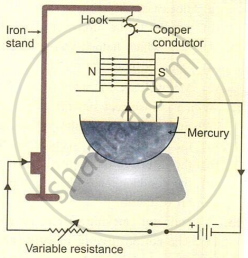
When the current is made to flow through a copper conductor, the direction of the magnetic field set up by the conductor is:
Parallel to the direction of magnetic field of permanent magnet.
At right angles to the direction of magnetic field of permanent magnet.
In any direction to the direction of magnetic field of permanent magnet.
None of these
Study the diagram alongside carefully and answer the following question:
Due to two magnetic fields, i.e., the permanent magnet and the magnetic field set up by the conductor, the force experienced by the conductor depends upon:
Strength of current flowing through conductor
Magnetic intensity of permanent magnet
Length of conductor within the pole pieces of permanent magnet
all of these
Study the diagram alongside carefully and answer the following question:
The direction in which the conductor will move is:
out of the plane of paper
inside the plane of paper
towards North pole
towards South pole
Study the diagram alongside carefully and answer the following question:
The law which helped you to find the direction of motion of the conductor is:
Fleming's right-hand rule
Fleming's left-hand rule
Maxwell’s cork screw rule
Right-hand thumb rule
Direction for Q. Numbers 20 to 24: The questions given below are Assertion (A) and Reason (R) type questions. Choose the correct answer from options given below:
Assertion (A): When a permanent bar magnet is placed in a solenoid connected to a.c. source, it gets demagnetised.
Reason (R): The alternating current rapidly changes the magnetic polarity which in turn disturbs magnetic molecular straight chains, to form closed chains and hence demagnetise the magnet.
Both Assertion (A) and Reason (R) are true and Reason (R) is the correct explanation of Assertion (A).
Both Assertion (A) and Reason (R) are true but Reason (R) is not the correct explanation of Assertion (A).
Assertion (A) is false, but Reason (R) is true.
Assertion (A) is true, but Reason (R) is false.
Assertion (A): A conductor carrying a current can produce an electrostatic field.
Reason (R): The net positive or negative charge on the conductor is zero.
Both Assertion (A) and Reason (R) are true and Reason (R) is the correct explanation of Assertion (A).
Both Assertion (A) and Reason (R) are true but Reason (R) is not the correct explanation of Assertion (A).
Assertion (A) is false, but Reason (R) is true.
Assertion (A) is true, but Reason (R) is false.
Assertion (A): A coil of many turns of an insulated copper wire is wound over soft iron core.
Reason (R): The strength of electromagnet increases with the increase in the magnitude of current.
Both Assertion (A) and Reason (R) are true and Reason (R) is the correct explanation of Assertion (A).
Both Assertion (A) and Reason (R) are true but Reason (R) is not the correct explanation of Assertion (A).
Assertion (A) is false, but Reason (R) is true.
Assertion (A) is true, but Reason (R) is false.
Assertion (A): In the presence of magnetic field, the needle of a compass aligns itself in the direction of magnetic field.
Reason (R): The needle of a compass always points in the north-south direction in the absence of any other magnetic field.
Both Assertion (A) and Reason (R) are true and Reason (R) is the correct explanation of Assertion (A).
Both Assertion (A) and Reason (R) are true but Reason (R) is not the correct explanation of Assertion (A).
Assertion (A) is false, but Reason (R) is true.
Assertion (A) is true, but Reason (R) is false.
Assertion (A): When a current flows through a metallic straight conductor, a magnetic field is set up at right angles to the direction of flow of current.
Reason (R): The flowing electrons act like tiny magnets.
Both Assertion (A) and Reason (R) are true and Reason (R) is the correct explanation of Assertion (A).
Both Assertion (A) and Reason (R) are true but Reason (R) is not the correct explanation of Assertion (A).
Assertion (A) is false, but Reason (R) is true.
Assertion (A) is true, but Reason (R) is false.
Complete the following sentences by choosing correct answers from brackets.
Magnetic lines of forces around a conductor carrying electric current are in the form of ______ lines.
parallel
circular
A coil facing you has current flowing in a clockwise direction. The face of coil will have ______ polarity.
North
South
A strong electromagnet has large number of turns wound over a ______ soft iron core.
solid
laminated
In an electric motor the electric energy changes to ______.
potential energy
magnetic energy
mechanical energy
By reversing the direction of current in an electromagnet the magnetic field produced by it ______.
increases
decreases
reverses
Match the statements in Column A with those in Column B.
| Column A | Column B |
|---|---|
| (a) Solenoid | (i) Name of rule for finding direction of magnetic field lines of force around a conductor carrying current. |
| (b) Ampere swimming Rule | (ii) An electrically operated device which can be easily magnetised or demagnetised . |
| (c) North | (iii) A current carrying cylindrical coil whose diameter is less than its length. |
| (d) Electromagnet | (iv) Name of rule used for detecting the direction of motion of magnetic needle under magnetic influence of conductor carrying current. |
| (e) Right hand thumb rule | (v) Magnetic polarity produced in a coil carrying current facing you, when direction of current is anticlockwise. |
Goyal Brothers Prakashan solutions for अ न्यू अप्रोच टू आईसीएसई [अंग्रेजी] कक्षा १० 9 1. Electromagnetism 2. Magnetic Effects of Electric Current 3. Electromagnetic Induction EXERCISE-2 [Pages 221 - 224]
- A transformer is designed to work on 200 V A.C mains, such that its output voltage is 6.0 V. Its primary coil has 6000 turns. Draw the fully labelled diagram of transformer.
- State the principle involved in the construction of the above transformer.
- Why is the secondary coil of this transformer far thicker than the primary coil?
- Why is the core of this transformer laminated?
- Can this transformer operate on 200 V D.C mains? Give a reason for your answer.
- Can the efficiency of this transformer be 100%? Explain your answer.
- How many turns are in the secondary coil?
Why do we need a step-up transformer for long-distance transmission of electric power?
Why is the e.m.f. at consuming centers dropped to 220 V by a step-down transformer?
State three characteristics of the primary coil of a step-up transformer.
State three characteristics of the secondary coil of a step-up transformer.
Figure alongside shows a coil connected to a centre zero galvanometer. The galvanometer shows deflection to the right, when the north pole of a powerful magnet is moved towards right.
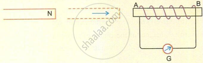
- Explain, why deflection occurs in the galvanometer?
- What is the direction of current when viewed from end A?
- What is your observation in G, when coil AB is moved from N?
- What is your observation in G, when both coil AB and the magnet are moved towards right at the same speed?
The given diagram shows the output of an AC generator. If the speed of the generator coil is doubled, then:

- what is the effect on the physical quantity indicated by ‘a’?
- what is the effect on the physical quantity indicated as ‘b’?
- give a reason for your answer in (b).
Which coil of a step up transformer is made thicker and why?
Name the transformer used in the power transmitting station of a power plant.
What is the nature of the current transmitted from the power station?
At what voltage is this current available to our household?
State two causes of energy loss in a transformer.
In the transmission of power the voltage of power generated at the generating stations is stepped up from 11kV to 132 kV before it is transmitted. Why?
How is the e.m.f. across primary and secondary coils of a transformer related with the number of turns of the coil in them?
On which type of current do transformers work?
Draw and label the diagram of an AC generator.
How is fluctuating current produced in an AC generator made smooth?
Answer the following question regarding an a.c. generator.
Why is the e.m.f. produced by the generator zero at a certain instant and maximum at some other instant when the coil is rotating at a constant speed?
Answer the following question regarding an a.c. generator.
When the current flowing in the external circuit is increased by decreasing the resistance, more power is required to drive the generator at the same speed. Explain.
What is an AC generator?
What is the function of the following in a dynamo?
Concave cylindrical magnets
What is the function of the following in a dynamo?
Laminated soft iron core
What is the function of the following in a dynamo?
Slip rings
What is the function of the following in a dynamo?
Brushes
On which phenomenon does the dynamo work? Define the phenomenon.
Explain the effect of current generated when magnetic field is increased.
Explain the effect of the current generated when the number of turns in the coil is increased.
In which position of the coil is the magnitude of the induced e.m.f. maximum?
In which position of the coil is the magnitude of the induced e.m.f. minimum?
The diagram below shows the core of a transformer and its input and output connections.
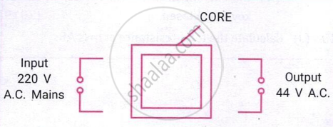
- State the material used for the core.
- Copy and complete the diagram of the transformer by drawing input and output coils.
State two dis-similarities between a d.c. motor and an a.c. generator.
A magnet kept at the centre of two coils A and B is moved to and fro as shown in the diagram. The two galvanometers show deflection. State with a reason whether : x > y or x< y [x and y are magnitudes of deflection.]

MULTIPLE CHOICE QUESTIONS Choose the most appropriate option.
The direction of current in a conductor can be obtained by:
Fleming’s right hand rule
Fleming’s left hand rule
Right hand thumb rule
Maxwell’s cork-screw rule
A coil is held in a magnetic field, such that plane of the coil is at right angles to that of the plane of permanent magnet. The force experienced by the coil on the passage of electric current will be:
maximum
zero
weak
none of these
The phenomenon of electromagnetic induction was discovered by:
Fleming
Maxwell
Faraday
Rutherford
Figure alongside shows insulated copper coil connected to centre zero galvanometer. The galvanometer shows deflection to the right when the north pole of a powerful magnet is moved to the right. Answer the following question:
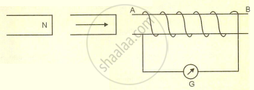
The galvanometer shows deflection because:
Movement of magnet towards right changes magnetic flux in the coil.
Due to change in magnetic flux, an induced e.m.f. is set in coil.
Due to induced e.m.f, induced current flows in circuit.
all of these.
Figure alongside shows insulated copper coil connected to centre zero galvanometer. The galvanometer shows deflection to the right when the north pole of a powerful magnet is moved to the right. Answer the following question:
When the movement of the magnet towards right stopped, then:
magnitude of induced current is zero
the galvanometer shows no deflection
no electromagnetic induction takes place
all of these
Figure alongside shows insulated copper coil connected to centre zero galvanometer. The galvanometer shows deflection to the right when the north pole of a powerful magnet is moved to the right. Answer the following question:
When the north pole of magnet is withdrawn towards left, the galvanometer shows:
no deflection
deflection towards right
deflection towards left
none of these
Figure alongside shows insulated copper coil connected to centre zero galvanometer. The galvanometer shows deflection to the right when the north pole of a powerful magnet is moved to the right. Answer the following question:
When the north pole of permanent magnet moves towards right the deflection of current in the coil is in:
clockwise direction
anticlockwise direction
direction is not certain
none of these.
Figure alongside shows insulated copper coil connected to centre zero galvanometer. The galvanometer shows deflection to the right when the north pole of a powerful magnet is moved to the right. Answer the following question:
The magnetic polarity induced at the end is:
north
south
can not say certainly
none of these
For an ideal step up transformer:
`"voltage"_"primary"/"voltage"_"secondary" gt 1`
`"current"_"primary"/"current"_"secondary" lt 1`
`"number of turns"_"primary"/"number of turns"_"secondary" = 1`
`"power"_"primary"/"power"_"secondary" = 1`
Direction for Q. Numbers 6 to 10: The questions given below are Assertion (A) and Reason (R) type questions. Choose the correct answer from options given below:
Assertion (A): The efficiency of a transformer is never 100%.
Reason (R): The energy is lost because of resistances of primary and secondary coils and eddy currents produced in core.
Both Assertion (A) and Reason (R) are true and Reason (R) is the correct explanation of Assertion (A).
Both Assertion (A) and Reason (R) are true but Reason (R) is not the correct explanation of Assertion (A).
Assertion (A) is false, but Reason (R) is true.
Assertion (A) is true, but Reason (R) is false.
Assertion (A): The a.c. motor is based on the principle of electromagnetic induction.
Reason (R): The direction of induced current in coil is given by Faraday's right hand rule.
Both Assertion (A) and Reason (R) are true and Reason (R) is the correct explanation of Assertion (A).
Both Assertion (A) and Reason (R) are true but Reason (R) is not the correct explanation of Assertion (A).
Assertion (A) is false, but Reason (R) is true.
Assertion (A) is true, but Reason (R) is false.
Assertion (A): More powerful is the inducing magnet, more is the magnitude of induced e.m.f. in a closed coil.
Reason (R): Magnetic energy of the powerful magnet changes into electric energy.
Both Assertion (A) and Reason (R) are true and Reason (R) is the correct explanation of Assertion (A).
Both Assertion (A) and Reason (R) are true but Reason (R) is not the correct explanation of Assertion (A).
Assertion (A) is false, but Reason (R) is true.
Assertion (A) is true, but Reason (R) is false.
Assertion (A): A single coil of many turns produces fluctuating e.m.f. in a.c. generator.
Reason (R): The coil in the a.c. generator is moving at a slow speed.
Both Assertion (A) and Reason (R) are true and Reason (R) is the correct explanation of Assertion (A).
Both Assertion (A) and Reason (R) are true but Reason (R) is not the correct explanation of Assertion (A).
Assertion (A) is false, but Reason (R) is true.
Assertion (A) is true, but Reason (R) is false.
Assertion (A): Primary coil of step up transformer is thinner as it has more turns than the secondary coil.
Reason (R): The induced e.m.f. produced in secondary coil is directly proportional to number of turns in the secondary coil.
Both Assertion (A) and Reason (R) are true and Reason (R) is the correct explanation of Assertion (A).
Both Assertion (A) and Reason (R) are true but Reason (R) is not the correct explanation of Assertion (A).
Assertion (A) is false, but Reason (R) is true.
Assertion (A) is true, but Reason (R) is false.
Complete the following sentences by choosing correct answers from brackets.
When the magnetic flux changes in a closed coil an ______ current is produced in the coil.
direct
induced
When the magnetic flux changes in a closed coil in an open circuit ______ induced current is produced.
large
less
no
About 10% of the energy is wasted in step up transformer, because of ______ produces in its core.
induced current
eddy current
The generating e.m.f at the power stations is ______ for transmission to consuming centres.
stepped up
stepped down
An a.c dynamo converts ______ energy into electric energy.
potential
magnetic
mechanical
Match the statements in Column A with those in Column B.
| Column A | Column B |
|---|---|
| (a) Electromagnetic induction | (i) A device in a d.c. motor which concentrates the magnetic lines of forces on the closed coil. |
| (b) Step-up Transformer | (ii) The name of energy which gets converted into electric energy in a dynamo. |
| (c) Slip rings | (iii) The phenomenon due to which changing magnetic flux produces an induced current in a closed coil. |
| (d) Mechanical Energy | (iv) A device which increase the e.m.f. of alternating current. |
| (e) Concave cylindrical Magnet | (v) A device in the a.c. dynamo which allows the induced current in the coil to pass on to external circuit. |
Goyal Brothers Prakashan solutions for अ न्यू अप्रोच टू आईसीएसई [अंग्रेजी] कक्षा १० 9 1. Electromagnetism 2. Magnetic Effects of Electric Current 3. Electromagnetic Induction COMPETENCY-FOCUSED PRACTICE QUESTIONS RELEASED BY CISCE [Pages 224 - 225]
The given rods will attract each other when:
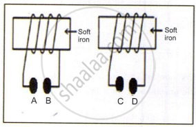
A and C are connected to positive terminal of the battery.
B and C are connected to the positive terminal of the battery.
A and D are connected to the positive terminal of the battery.
A and D are connected to the negative terminal of the battery.
A magnetic compass is present on a small table, very close to the wall in a room. A man enters the room and switches on the Air Conditioner fitted near the ceiling. He observes that the needle in the compass shows immediate deflection. Identify the most probable reason for the deflection.
Air blowing in the room.
Current starts flowing through AC wire concealed in the adjacent wall.
Vibrations are produced when the Man starts talking to his wife in the kitchen.
Vibrations were produced due to a file in his hand that fell on the ground.
Assertion (A): When current is passed through a wire, a magnetic field is generated around the wire.
Reason (R): Whenever there is a change of magnetic flux linked up with the coil, the induced current is generated in the coil.
Both A and R are correct, and R is the correct explanation of A.
Both A and R are correct, but R is not the correct explanation of A.
A is correct but R is wrong.
Both A and R are wrong.
A straight wire is passed vertically through cardboard sprinkled with iron filings.
- When current is passed through the wire in the upward direction, it is seen that the iron fillings are arranging themselves in a definite pattern. Why?
- What would happen to this arrangement if more current were passed through the wire?
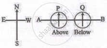
The diagram shows a copper conductor placed along the east-west direction. Magnetic compass P is present above the conductor, and Q is below the conductor. If current is passed through the wire from A to B, then which of the two compasses will show prominent deflection and why?
Read the excerpt from a story and answer the questions that follow:
| On stage, a soft iron box sits atop a hidden copper coiled platform, conductive to electricity. I summoned a man who fancied himself a modern-day Hercules onto the stage and challenged him to lift the iron box. With ease, he lifted it up. Then, with a wave of my magic wand and a hidden switch activated, I said, “I’m going to take away your strength.” When I asked him to lift the box again, he struggled, unable to budge it. |
- Explain the secret behind the magic.
- If you are asked to design the same magic in your science lab, give the necessary circuit diagram.
- Give any one device that works on the same principle.
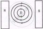
In the given diagram, X represents a conductor carrying current into the plane of the paper and kept in a magnetic field. N and S represent the poles of a magnet and the concentric circles of the magnetic field produced by the conductor.
- State the direction of the force experienced by the conductor.
- Explain the cause of the above-said force.
- Name the law used to determine the direction of the force in the conductor.
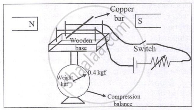
The circuit diagram illustrates a copper bar placed on two copper wires stretched over a wooden base placed between two poles of magnets. This entire setup is placed on a compression balance, which shows a weight of 0.4 kgf.
- What will be the observation of the compression balance when we close the switch?
- How will this observation change when we increase the current in the circuit?
- Name the rule used to come to the conclusion in (a).

The diagram shows two parallel wires carrying current in the downward direction. The magnitude of the current in wire A is greater than in wire B. It is also observed that the wires exert force on each other.
- State the direction of the force experienced by wire A.
- Name the law/laws used to come to the conclusion in (a).
- When a compass is placed between the two wires, it does not remain along the direction of the magnetic field of wire A or wire B at one of the points P, Q, or R. State, with a reason, at which point you will observe this.
Solutions for 9: 1. Electromagnetism 2. Magnetic Effects of Electric Current 3. Electromagnetic Induction
Goyal Brothers Prakashan solutions for अ न्यू अप्रोच टू आईसीएसई [अंग्रेजी] कक्षा १० chapter 9 - 1. Electromagnetism 2. Magnetic Effects of Electric Current 3. Electromagnetic Induction
Shaalaa.com has the CISCE Mathematics अ न्यू अप्रोच टू आईसीएसई [अंग्रेजी] कक्षा १० CISCE solutions in a manner that help students grasp basic concepts better and faster. The detailed, step-by-step solutions will help you understand the concepts better and clarify any confusion. Goyal Brothers Prakashan solutions for Mathematics अ न्यू अप्रोच टू आईसीएसई [अंग्रेजी] कक्षा १० CISCE 9 (1. Electromagnetism 2. Magnetic Effects of Electric Current 3. Electromagnetic Induction) include all questions with answers and detailed explanations. This will clear students' doubts about questions and improve their application skills while preparing for board exams.
Further, we at Shaalaa.com provide such solutions so students can prepare for written exams. Goyal Brothers Prakashan textbook solutions can be a core help for self-study and provide excellent self-help guidance for students.
Concepts covered in अ न्यू अप्रोच टू आईसीएसई [अंग्रेजी] कक्षा १० chapter 9 1. Electromagnetism 2. Magnetic Effects of Electric Current 3. Electromagnetic Induction are Applications of Biot-Savart's Law > Magnetic Field Due to a Straight Current-carrying Conductor of Finite Size, Right-hand Thumb Rule, Applications of Ampere’s Circuital Law > Magnetic Field of a Long Straight Solenoid, Permanent Magnet, Uses of Electromagnet, Simple D.C. Motor, Introduction to Electromagnetic Induction, Faraday's Laws of Electromagnetic Induction, Force on a Current-Carrying Conductor Placed in a Uniform Magnetic Field, Alternating-Current Generator, Comparison Between A.C. Generator and D.C. Motor, Transformers, Oersted's Experiment, Electromagnet, Frequency of an a.c. in Household Supplies, Comparison of an Electro Magnet with a Permanent Magnet, Advantages of an Electromagnet over a Permanent Magnet, Electromagnetic Induction: Experimental Demonstration, Faraday's Explanation, Applications of Biot-Savart's Law > Magnetic Field at the Axis of a Circular Current-carrying Loop.
Using Goyal Brothers Prakashan अ न्यू अप्रोच टू आईसीएसई [अंग्रेजी] कक्षा १० solutions 1. Electromagnetism 2. Magnetic Effects of Electric Current 3. Electromagnetic Induction exercise by students is an easy way to prepare for the exams, as they involve solutions arranged chapter-wise and also page-wise. The questions involved in Goyal Brothers Prakashan Solutions are essential questions that can be asked in the final exam. Maximum CISCE अ न्यू अप्रोच टू आईसीएसई [अंग्रेजी] कक्षा १० students prefer Goyal Brothers Prakashan Textbook Solutions to score more in exams.
Get the free view of Chapter 9, 1. Electromagnetism 2. Magnetic Effects of Electric Current 3. Electromagnetic Induction अ न्यू अप्रोच टू आईसीएसई [अंग्रेजी] कक्षा १० additional questions for Mathematics अ न्यू अप्रोच टू आईसीएसई [अंग्रेजी] कक्षा १० CISCE, and you can use Shaalaa.com to keep it handy for your exam preparation.
