Advertisements
Advertisements
प्रश्न
Match the column ‘A’ with column ‘B’.
|
Column ‘A’
|
Column ‘B’ |
|
(1) Eka - boron
|
(a) Germanium
|
|
(2) Eka - Aluminium
|
(b) Scandium
|
|
(3) Eka - Silicon
|
(c) Gallium |
Advertisements
उत्तर
|
Column ‘A’
|
Column ‘B’
|
|
(1) Eka - boron
|
(b) Scandium |
|
(2) Eka - Aluminium
|
(c) Gallium |
|
(3) Eka - Silicon
|
(a) Germanium |
APPEARS IN
संबंधित प्रश्न
What do the following symbols mean in circuit diagrams?
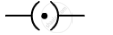
What is a circuit diagram
Draw a circuit diagram to show how 3 bulbs can be lit from a battery so that 2 bulbs are controlled by the same switch the third bulb has its own switch.
Explain with the help of a labelled circuit diagram how you will find the resistance of a combination of three resistors, or resistance R1, R2 and R3, joined in parallel. Also mention how you will connect the ammeter and the voltmeter in the circuit when measuring the current in the circuit and the potential difference across one of the three resistors of the combination.
How does the short circuit form?
Who will spend more electrical energy? 500 W TV Set in 30 mins, or 600 W heater in 20 mins?
The following figure shows the symbols for components used in the accompanying electrical circuit. Place them at proper places and complete the circuit.
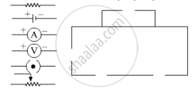
Which law can you prove with the help of above circuit?
A battery is to be formed by joining 3 dry cells with connecting wires. Show how will you connect the wires by drawing a diagram.
In an electric circuit, a battery and a bulb have been connected and the battery consists of two cells of equal potential difference. If the bulb is not glowing, then which tests will you perform in order to find out the reason for the bulb not glowing?
Find the odd one out and give its explanation.
How much is the potential difference between live and neutral wires?
Right or wrong sentence.
Increasing the current passing through the wire decreases the magnetic field intensity.
Nowadays MCBs are used in homes, for stop the current in the circuit which suddenly increases.
Write scientific reason.
It is beneficial to carry electrical energy in AC form as it is carried over long distances.
______ is the device used to close or open an electric circuit.
In which among the following circuits does the bulb glow?
In which of the following circuits are the bulb connected in series?
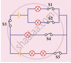
Study the electric circuit below. Which of the following switches should be closed so that only two bulbs will light up
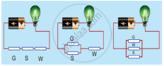
Study the three electric circuits below. Each of them has a glass rod (G), a steel rod (S), and a wooden rod (W).
In which of the electric circuits would the bulb not light up.
Which of the following a simple circuit must-have?
In a simple circuit, why does the bulb glow when you close the switch?
When a circuit is open, _____ cannot pass through it.
What is the role of the earth wire in domestic circuits?
In a circuit, if the key is in open (off) condition, then electricity will not flow.
In an electrical circuit three incandescent bulbs A, B and C of rating 40 W, 60 W and 100 W respectively are connected in parallel to an electric source. Which of the following is likely to happen regarding their brightness?
Three bulbs A, B, C are connected in a circuit as shown in the following figure. When the switch is ‘ON’
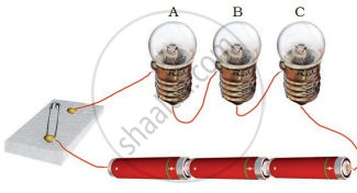
In an electric circuit a fuse is a ______ ______ to prevent possible fire.
Draw the symbols of the following circuit components.
Switch in off position
Observe the circuit given:
1. Would any of the bulbs glow when the switch is in the ‘OFF’ position?
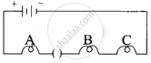
2. What will be the order in which the bulbs A, B, and C will glow when the switch is moved to the ‘ON’ position?

In the above circuit, if the current reading in the ammeter A is 2A, what would be the value of R1?
The ______ is a species of fish that can give electric shocks of up to six hundred fifty watts of electricity.
Match the following
| 1. | Insulator | a. | Coulomb |
| 2. | Conductor | b. | Electric circuit |
| 3. | Closed path | c. | Copper |
| 4. | Electric charge | d. | Rubber |
What are the essential components of an electric circuit?
A complete circuit is left on for several minutes, causing the connecting copper wire to become hot. As the temperature of the wire increases, the electrical resistance of the wire
How is Joule's law effect useful in electric circuits where fuse is used as a safety device?
