Advertisements
Advertisements
प्रश्न
The following figure shows the symbols for components used in the accompanying electrical circuit. Place them at proper places and complete the circuit.
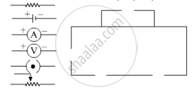
Which law can you prove with the help of above circuit?
Advertisements
उत्तर

Electrical circuit showing the connection of various components
The above circuit can be proved by Ohm's law.
Ohm’s law The relationship between the current flowing through a wire (I) and the potential difference across its ends (V) can be obtained from the law that was given by the German scientist George Simon Ohm.
APPEARS IN
संबंधित प्रश्न
What do the following symbols mean in circuit diagrams?
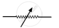
Draw circuit symbols for variable resistance
What is a circuit diagram
Tell the odd one out. Give a proper explanation.
Explain the construction and working of the following. Draw a neat diagram and label it.
Electric motor
How does the short circuit form?
The accompanying figure shows some electrical appliances connected in a circuit in a house. Answer the following questions.

- By which method are the appliances connected?
- What must be the potential difference across individual appliances?
- Will the current passing through each appliance be the same? Justify your answer.
- Why are the domestic appliances connected in this way?
- If the T.V. stops working, will the other appliances also stop working? Explain your answer.
Distinguish between a closed circuit and an open circuit, with the use of suitable labelled diagrams.
Write the condition required for a circuit to be a closed circuit.
What do you understand by the closed electric circuit
The unit of electrical power is _______.
What is the use of earthing wire?
In which among the following circuits does the bulb glow?
Assertion: People struck by lightning receive a severe electrical shock.
Reason: Lightning carries very high voltage.
The wiring in a house consists of ______ circuits.
The rate of flow of electric charges in a circuit is called ______.
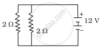
In the following circuits (Figure), heat produced in the resistor or combination of resistors connected to a 12 V battery will be
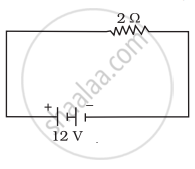 |
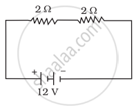 |
 |
| (i) | (ii) | (iii) |
In an electric circuit, the current starts from ______.
In an electric circuit a fuse is a ______ ______ to prevent possible fire.
Write a short note on the different electrical circuits.
