Advertisements
Advertisements
प्रश्न
A cylindrical capacitor has two co-axial cylinders of length 15 cm and radii 1.5 cm and 1.4 cm. The outer cylinder is earthed and the inner cylinder is given a charge of 3.5 µC. Determine the capacitance of the system and the potential of the inner cylinder. Neglect end effects (i.e., bending of field lines at the ends).
Advertisements
उत्तर
Length of a co-axial cylinder, l = 15 cm = 0.15 m
Radius of outer cylinder, r1 = 1.5 cm = 0.015 m
Radius of inner cylinder, r2 = 1.4 cm = 0.014 m
Charge on the inner cylinder, q = 3.5 µC = 3.5 × 10⁻⁶ C
Capacitance of a co-axial cylinder of radii r1 and r2 is given by relation
C = `(2piin_0"l")/log_"e"("r"_1/"r"_2)`
Where,
`in_0` = Permittivity of free space = `8.85 xx 10^-12 "N"^-1 "m"^-2 "C"^2`
∴ C = `(2pi xx 8.85 xx 10^-12 xx 0.15)/(2.3026 log_10(0.15/0.14))`
= `(2pi xx 8.85 xx 10^-12 xx 0.15)/(2.3026 xx 0.0299) = 1.2 xx 10^-10 "F"`
Potential difference of the inner cylinder is given by,
`"V" = "q"/"C"`
= `(3.5 xx 10^-6)/(1.2 xx 10^-10) = 2.92 xx 10^4 "V"`
APPEARS IN
संबंधित प्रश्न
Two capacitors of unknown capacitances C1 and C2 are connected first in series and then in parallel across a battery of 100 V. If the energy stored in the two combinations is 0.045 J and 0.25 J respectively, determine the value of C1 and C2. Also calculate the charge on each capacitor in parallel combination.
Three capacitors each of capacitance 9 pF are connected in series.
- What is the total capacitance of the combination?
- What is the potential difference across each capacitor if the combination is connected to a 120 V supply?
Figure 4 below shows a capacitor C, an inductor L and a resistor R, connected in series
to an a.c. supply of 220 V
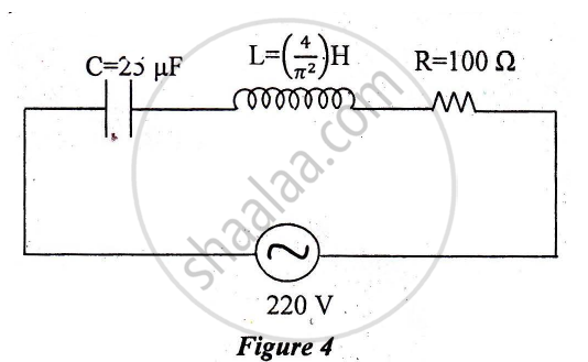
Calculate:
1) The resonant frequency of the given CLR circuit.
2) Current flowing through·the circuit.
3) Average power consumed by the circuit.
A circuit is set up by connecting inductance L = 100 mH, resistor R = 100 Ω and a capacitor of reactance 200 Ω in series. An alternating emf of \[150\sqrt{2}\] V, 500/π Hz is applies across this series combination. Calculate the power dissipated in the resistor.
If the capacitors in the previous question are joined in parallel, the capacitance and the breakdown voltage of the combination will be
A parallel-plate capacitor having plate area 20 cm2 and separation between the plates 1⋅00 mm is connected to a battery of 12⋅0 V. The plates are pulled apart to increase the separation to 2⋅0 mm. (a) Calculate the charge flown through the circuit during the process. (b) How much energy is absorbed by the battery during the process? (c) Calculate the stored energy in the electric field before and after the process. (d) Using the expression for the force between the plates, find the work done by the person pulling the plates apart. (e) Show and justify that no heat is produced during this transfer of charge as the separation is increased.
A capacitor of capacitance 5⋅00 µF is charged to 24⋅0 V and another capacitor of capacitance 6⋅0 µF is charged to 12⋅0 V. (a) Find the energy stored in each capacitor. (b) The positive plate of the first capacitor is now connected to the negative plate of the second and vice versa. Find the new charges on the capacitors. (c) Find the loss of electrostatic energy during the process. (d) Where does this energy go?
An ac circuit consists of a series combination of circuit elements X and Y. The current is ahead of the voltage in phase by `pi/4`. If element X is a pure resistor of 100 Ω,
(a) name the circuit element Y.
(b) calculate the rms value of current, if rms of voltage is 141 V.
(c) what will happen if the ac source is replaced by a dc source
Two parallel plate capacitors X and Y, have the same area of plates and same separation between plates. X has air and Y with dielectric of constant 2, between its plates. They are connected in series to a battery of 12 V. The ratio of electrostatic energy stored in X and Y is ______.
Capacitors connected in series have ______
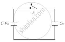
A capacitor of capacity C1 is charged to the potential of V0. On disconnecting with the battery, it is connected with an uncharged capacitor of capacity C2 as shown in the adjoining figure. Find the ratio of energies before and after the connection of switch S.
Three capacitors of capacitances 2 pF, 3 pF and 4 pF are connected in parallel. What is the total capacitance of the combination?
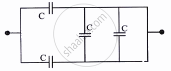
The equivalent capacitance of the combination shown is:
What is the work done per unit charge in moving a charge from one plate of a capacitor to the other called?
What is the charge relationship for capacitors in series?
What is the equivalent capacitance of \[n\] identical capacitors, each with capacitance \[C\], connected in series?
In a series combination, which capacitor has the larger voltage drop?
Which formula gives the equivalent capacitance of capacitors in parallel?
What is the equivalent capacitance of \[n\] identical capacitors, each with capacitance \[C\], connected in parallel?
A charge of \[1.6\times10^{-11}\,\mathrm{C}\] produces a potential difference of \[10\,\mathrm{V}\]. What capacitance follows from \[C=\frac{Q}{V}\]?
