Advertisements
Advertisements
Question
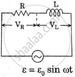
What will be the potential difference in the circuit when direct current is passed through the circuit?
Advertisements
Solution
In case of DC ω = 0
XL = ωL = 0 Ω R = 160 Ω
Z = 160 Ω
e = 160 × i
e = 160V
APPEARS IN
RELATED QUESTIONS
A series LCR circuit is connected to an ac source. Using the phasor diagram, derive the expression for the impedance of the circuit. Plot a graph to show the variation of current with frequency of the source, explaining the nature of its variation.
Draw a labelled graph showing a variation of impedance of a series LCR circuit with frequency of the a.c. supply.
Answer the following question.
What is the phase difference between the voltages across the inductor and the capacitor at resonance in the LCR circuit?
Derive an expression for the average power dissipated in a series LCR circuit.
Choose the correct answer from given options
The phase difference between the current and the voltage in series LCR circuit at resonance is
Figure shows a series LCR circuit connected to a variable frequency 230 V source. L = 5.0 H, C = 80 µF, R = 40 Ω.
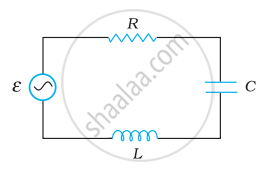
- Determine the source frequency which drives the circuit in resonance.
- Obtain the impedance of the circuit and the amplitude of current at the resonating frequency.
- Determine the rms potential drops across the three elements of the circuit. Show that the potential drop across the LC combination is zero at the resonating frequency.
The resonant frequency of a RF oscillator is 1 MHz and its bandwidth is 10 kHz. The quality factor will be :
In series LCR circuit, the plot of Imax vs ω is shown in figure. Find the bandwidth and mark in the figure.

To reduce the resonant frequency in an L-C-R series circuit with a generator ______.
A 20Ω resistance, 10 mH inductance coil and 15µF capacitor are joined in series. When a suitable frequency alternating current source is joined to this combination, the circuit resonates. If the resistance is made \[\frac {1}{3}\] rd, the resonant frequency ______.
