Advertisements
Advertisements
Question
The circuit diagram in fig shows two coils of an insulated copper wire wound on a cardboard tube. G is a center zero galvanometer.
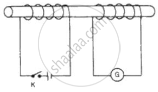
(a) Describe what will happen when th e swi tch K is cl osed for severa l
seconds and then opened again .
(b) What will be the effect of repeating the experiment with an iron placed in the tube?
Advertisements
Solution
(a) We will observe that the needle of the galvanometer instantly jumps to one side and just as quickly returns to zero, indicating a momentary current in coil connected to galvanometer.
(b) Introducing an iron bar in the tube, will increase the amount of induced current and the galvanometer will show a greater deflection.
APPEARS IN
RELATED QUESTIONS
Draw the electrical symbols of the following components and state its use
Wire crossing
What is an electric current?
Why should the resistance of:
a voltmeter be very large?
Two resistors of 4 Ω and 6 Ω are connected in parallel. The combination is
connected across a 6 volt battery of negligible resistance. Calculate:
( i) The power supplied by the battery,
(ii) The power dissipated in each resistor.
Define the term kilowatt - hour and state its value in S.I. unit.
Two electric bulbs rated 100 W; 220 V and 60 W; 220 V are connected in parallel to electric mains of 220 V. Find the current drawn by the bulbs from the mains.
Explain, why the potential difference across the terminals of a cell is more when the cell is not in use than it is when the cell is being used.
An electric bulb is marked 100 W, 250 V. How much current will the bulb draw if connected to a 250 V supply?
Define the following:
Conventional current
