Advertisements
Advertisements
Question
The accompanying figure shows some electrical appliances connected in a circuit in a house. Answer the following questions.

- By which method are the appliances connected?
- What must be the potential difference across individual appliances?
- Will the current passing through each appliance be the same? Justify your answer.
- Why are the domestic appliances connected in this way?
- If the T.V. stops working, will the other appliances also stop working? Explain your answer.
Advertisements
Solution
- The appliances are connected in parallel.
- The potential difference between all appliances is the same with a parallel connection.
- No, because each appliance has a different load (resistance), the current passing through them will differ.
- Domestic appliances are connected in parallel because the potential difference remains constant.
- No, the other devices will continue working since the current passing through them follows separate routes.
APPEARS IN
RELATED QUESTIONS
Draw circuit symbols for
fixed resistance
How does the short circuit form?
Find the odd one out and justify it.
Fuse wire, M.C.B., Rubber Gloves, Generator
The following figure shows the symbols for components used in the accompanying electrical circuit. Place them at proper places and complete the circuit.
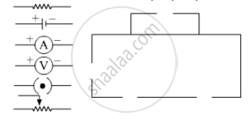
Which law can you prove with the help of above circuit?
What do you understand by the open electric circuit?
Explain the following:
Open circuit
In any electric circuit, when the switch is on and the current flows through it why do the wire, switches, bulb or devices become hot?
Tabulate the different components of an electric circuit and their respective symbols.
In which among the following circuits does the bulb glow?
Fuse is
Explain about domestic electric circuits. (circuit diagram not required)
What are the types of electric circuits?
In an electrical circuit two resistors of 2 Ω and 4 Ω respectively are connected in series to a 6 V battery. The heat dissipated by the 4 Ω resistor in 5 s will be
Our body is a ______ of electricity.

In the above circuit, if the current reading in the ammeter A is 2A, what would be the value of R1?
Match the following
| 1. | Insulator | a. | Coulomb |
| 2. | Conductor | b. | Electric circuit |
| 3. | Closed path | c. | Copper |
| 4. | Electric charge | d. | Rubber |
