Advertisements
Advertisements
Question
Redraw the circuit of question 1, putting in an ammeter to measure the current through the resistors and a voltmeter to measure the potential difference across the 12 Ω resistors. What would be the readings in the ammeter and the voltmeter?
Advertisements
Solution
An ammeter should be connected in the circuit in series with the resistors. To measure the potential difference across the resistor it should be connected in parallel, as shown in the following figure.

The resistances are connected in series.
Ohm’s law can be used to obtain the readings of ammeter and voltmeter.
According to Ohm’s law,
V = IR,
Where,
Potential difference, V = 6 V
Current flowing through the circuit/resistors = I
Resistance of the circuit, R = 5 + 8 + 12 = 25Ω
I = `V/R`
= `6/25`
= 0.24 A
Potential difference across 12 Ω resistor = V1
Current flowing through the 12 Ω resistor, I = 0.24 A
Therefore, using Ohm’s law, we obtain
V1 = IR
= 0.24 × 12
= 2.88 V
Therefore, the reading of the ammeter will be 0.24 A.
The reading of the voltmeter will be 2.88 V.
RELATED QUESTIONS
Draw circuit symbols for
a cell
Draw circuit symbols for
an open switch
Draw a circuit diagram to show how 3 bulbs can be lit from a battery so that 2 bulbs are controlled by the same switch the third bulb has its own switch.
The accompanying figure shows some electrical appliances connected in a circuit in a house. Answer the following questions.

- By which method are the appliances connected?
- What must be the potential difference across individual appliances?
- Will the current passing through each appliance be the same? Justify your answer.
- Why are the domestic appliances connected in this way?
- If the T.V. stops working, will the other appliances also stop working? Explain your answer.
What do you understand by the closed electric circuit
What do you understand by the open electric circuit?
The unit of electrical power is _______.
Find the odd one out and give its explanation.
Draw the circuit diagram for the series connection.
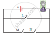
In the circuit shown, which switches (L,M or N) must be closed to light up the bulb?
Assertion: In an open circuit, the current passes from one terminal of the electric cell to another.
Reason: Generally, the metal disc of a cell acts as a positive terminal.
In a circuit, if the key is in open (off) condition, then electricity will not flow.
What are the types of electric circuits?
In an electrical circuit three incandescent bulbs A, B and C of rating 40 W, 60 W and 100 W respectively are connected in parallel to an electric source. Which of the following is likely to happen regarding their brightness?
Choose the statement which is not correct in the case of an electric fuse.
Our body is a ______ of electricity.
What are the essential components of an electric circuit?
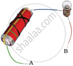
In the following arrangement shown in the following figure, the bulb will not glow if the ends A and B are connected with
Name the device which is used to measure the strength of the electric current in an electric circuit.
Set up the circuit shown in Figure again. Move the key to ‘ON’ position and watch carefully in which direction the compass needle gets deflected. Switch ‘OFF’ the current. Now keeping rest of the circuit intact, reverse the connections at the terminal of the cell. Again switch ‘on’ the current. Note the direction in which the needle gets deflected. Think of an explanation.