Advertisements
Advertisements
Question
Draw a labeled diagram of a full wave rectifier circuit. State its working principle. Show the input-output waveforms ?
Advertisements
Solution
To get an output voltage for both half cycles of the input signal, we use full wave rectifiers. The commonly used full wave rectifier circuits are center-tap rectifier and bridge rectifier. The figure below shows the center-tap rectifier circuit.
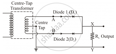
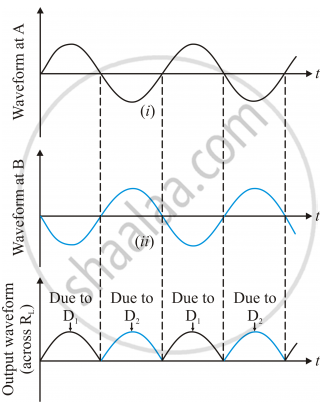
Now consider the circuit. The P-side of the diodes D1 and D2 are connected to the secondary terminals of the transformer. The N-sides of the diodes are connected together. The load is connected between this point and the midpoint of the transformer. When the input signal to diode D1 is positive, it conducts and load current flows. During this time, the input to diode D2 is negative with respect to the midpoint. During the negative half cycle of the input signal, the voltage at D1 is negative and that at D2 is positive. So D2 conducts during this time period. Thus we get output voltage during both the half cycles. As the full wave rectifier rectifies both the half cycles, it is more efficient than the half wave rectifier. The waveforms are given below:
APPEARS IN
RELATED QUESTIONS
Derive an expression for e.m.f. and current in terms of turns ratio
Name two factors on which the magnitude of an induced e.m.f. in the secondary coil depends.
The transformer is used in ______ current circuits.
The input and output voltage of a transformer are 220 V and 44 V respectively. Find: the turns ratio.
What is the turns ratio i.e., transformer ratio, ns: np, in an ideal transformer which in-creases ac voltage from 220 V to 33000 V?
Mention the various energy losses in a transformer.
Which among the following, is not a cause for power loss in a transformer?
1 MW power is to be delivered from a power station to a town 10 km away. One uses a pair of Cu wires of radius 0.5 cm for this purpose. Calculate the fraction of ohmic losses to power transmitted if
- power is transmitted at 220 V. Comment on the feasibility of doing this.
- a step-up transformer is used to boost the voltage to 11000 V, power transmitted, then a step-down transfomer is used to bring voltage to 220 V. (ρCu = 1.7 × 10⁻⁸ SI unit)
