Advertisements
Advertisements
प्रश्न
Draw a labeled diagram of a full wave rectifier circuit. State its working principle. Show the input-output waveforms ?
Advertisements
उत्तर
To get an output voltage for both half cycles of the input signal, we use full wave rectifiers. The commonly used full wave rectifier circuits are center-tap rectifier and bridge rectifier. The figure below shows the center-tap rectifier circuit.
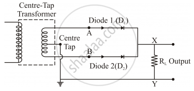
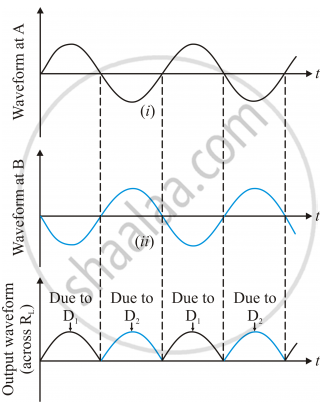
Now consider the circuit. The P-side of the diodes D1 and D2 are connected to the secondary terminals of the transformer. The N-sides of the diodes are connected together. The load is connected between this point and the midpoint of the transformer. When the input signal to diode D1 is positive, it conducts and load current flows. During this time, the input to diode D2 is negative with respect to the midpoint. During the negative half cycle of the input signal, the voltage at D1 is negative and that at D2 is positive. So D2 conducts during this time period. Thus we get output voltage during both the half cycles. As the full wave rectifier rectifies both the half cycles, it is more efficient than the half wave rectifier. The waveforms are given below:
APPEARS IN
संबंधित प्रश्न
A power transmission line feeds input power at 2200 V to a step-down transformer with its primary windings having 300 turns. Find the number of turns in the secondary to get the power output at 220 V.
The input and output voltage of a transformer are 220 V and 44 V respectively. Find: the turns ratio.
Name three losses of energy in a transformer. How are they minimized?
(i) Draw a clear labelled diagram of an electric bell.
(ii) Explain in brief, its working.
(iii) What material is used for the core of an electric bell? State the reason.
A circular coil of 100 turns with a cross-sectional area of 1 m2 is kept with its plane perpendicular to the magnetic field of 1 T. The magnetic flux linkage is ______.
State whether true or false. If false, correct the statement.
A transformer can step up direct current.
The line that draws power supply to your house from street has ______.
- zero average current.
- 220 V average voltage.
- voltage and current out of phase by 90°.
- voltage and current possibly differing in phase `phi` such that `|phi| < pi/2`.
Magnetic flux passing through a coil is initially 4 × 10⁻⁴ Wb. It reduces to 10% of its original value in t second. If the emf induced is 0. 72 mV then t in second is ______.
The primary coil of a transformer has 60 turns whereas its secondary coil has 3000 turns.
If a current of 5A flows in the primary coil, how much current will flow in a load in the secondary coil? State the assumption you have made regarding the transformer, in this calculation.
