Advertisements
Advertisements
प्रश्न
Draw a labeled diagram of a full wave rectifier circuit. State its working principle. Show the input-output waveforms ?
Advertisements
उत्तर
To get an output voltage for both half cycles of the input signal, we use full wave rectifiers. The commonly used full wave rectifier circuits are center-tap rectifier and bridge rectifier. The figure below shows the center-tap rectifier circuit.
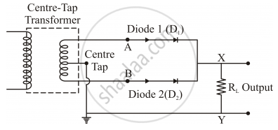
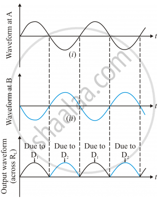
Now consider the circuit. The P-side of the diodes D1 and D2 are connected to the secondary terminals of the transformer. The N-sides of the diodes are connected together. The load is connected between this point and the midpoint of the transformer. When the input signal to diode D1 is positive, it conducts and load current flows. During this time, the input to diode D2 is negative with respect to the midpoint. During the negative half cycle of the input signal, the voltage at D1 is negative and that at D2 is positive. So D2 conducts during this time period. Thus we get output voltage during both the half cycles. As the full wave rectifier rectifies both the half cycles, it is more efficient than the half wave rectifier. The waveforms are given below:
APPEARS IN
संबंधित प्रश्न
The teachers of Geeta’s school took the students on a study trip to a power generating station, located nearly 200 km away from the city. The teacher explained that electrical energy is transmitted over such a long distance to their city, in the form of alternating current (ac) raised to a high voltage. At the receiving end in the city, the voltage is reduced to operate the devices. As a result, the power loss is reduced. Geeta listened to the teacher and asked questions about how the ac is converted to a higher or lower voltage.
1) Name the device used to change the alternating voltage to a higher or lower value. State one cause for power dissipation in this device.
2) Explain with an example, how power loss is reduced if the energy is transmitted over long distances as an alternating current rather than a direct current.
3) Write two values each shown by the teachers and Geeta.
Explain the significance of Lenz’s law to show the conservation of energy in electromagnetic induction.
Describe briefly and two energy losses, giving the reasons for their occurrence in actual transformers ?
The input and output voltages of a transformer are 220 V and 44V respectively. Find the current in input circuit if the output current is 2 A.
What is the ideal transformer?
Explain step up and step down transformer?
State whether true or false. If false, correct the statement.
A transformer can step up direct current.
The magnetic flux through a coil perpendicular to its plane is varying according to the relation Φ = (5t3 + 4t2 + 2t - 5) Weber. If the resistant of the coil is 5 ohm, then the induced current through the coil at t = 2 sec will be ______.
The primary coil of a transformer has 60 turns whereas its secondary coil has 3000 turns.
If a 220 V ac voltage is applied to the primary coil, how much emf is induced in the secondary coil?
For what purpose are the transformers used?
